
Subscribe to Our Youtube Channel
Related Manuals for SICK A3M60 Advanced


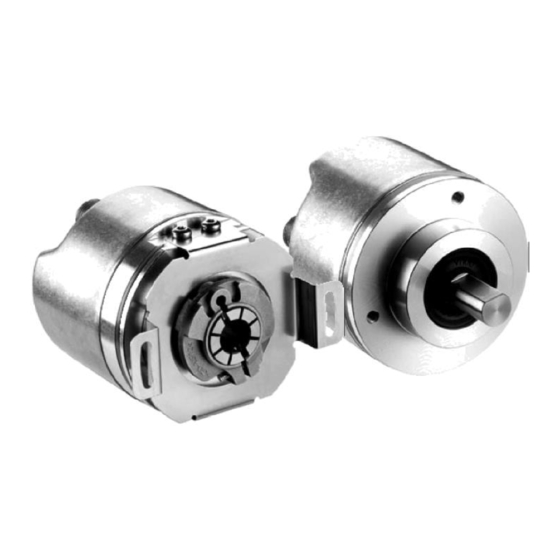
Summary of Contents for SICK A3M60 Advanced
- Page 1 O P E R A T I N G I N S T R U C T I O N S A3M60 Advanced PROFIBUS Absolute Encoder...
- Page 2 This document is protected by the law of copyright. Whereby all rights established therein remain with the company SICK AG. Reproduction of this document or parts of this document is only permissible within the limits of the legal determination of Copyright Law. Alteration or abridgement of the document is not permitted without the explicit written approval of the company SICK AG.
-
Page 3: Table Of Contents
Number of revolutions, nominator for the round axis functionality ................... 24 3.6.16 Number of revolutions, divisor for the round axis functionality ................... 24 Controls and status indicators ................ 24 8014117/1EF3/2012-12-08 © SICK AG • Germany • All rights reserved Subject to change without notice... - Page 4 Error messages via acyclic services ..........38 Technical specifications .................... 39 Data sheet ..................... 39 Dimensional drawings ..................41 6.2.1 A3M60 Advanced with blind hollow shaft ........41 6.2.2 A3M60 Advanced with servo flange ..........41 6.2.3 A3M60 Advanced with face mount flange ........42 Ordering information ....................
-
Page 5: About This Document
The operating instructions are addressed at the designers, developers and operators of systems in which one or more A3M60 Advanced PROFIBUS Absolute Encoders are to be integrated. They also address people who are in charge of commissioning or servicing and maintaining the A3M60 Advanced. -
Page 6: Scope
PROFIBUS System Description (Vers. 10/2002), Order No. 4.002 Scope These operating instructions are original operating instructions. Note These operating instructions apply to the A3M60 Advanced PROFIBUS Absolute Encoders with the type identifier A3M60A<xxx. Abbreviations used Decentralized Periphery Electrically Erasable Programmable Read-only Memory... -
Page 7: On Safety
PROFIBUS DP network. In case of any other usage as well as in case of modifications to the A3M60 Advanced, e.g. due to opening the housing during mounting and electrical installation, or to the SICK software, any claims against SICK AG under the warranty will be rendered void. -
Page 8: General Safety Notes And Protective Measures
Tab. 2: Disposal of the Assembly Material Disposal assemblies Packaging Cardboard Waste paper Shaft Stainless steel Scrap metal Flange Aluminium Scrap metal Electronic assemblies Various Hazardous waste © SICK AG • Germany • All rights reserved 8014117/1EF3/2021-12-08 Subject to change without notice... -
Page 9: Product Description
– The encoder supports the isochronous mode as per DP<V2. The A3M60 Advanced supports the encoder profile V4.1 class 3 and 4. The A3M60 Advanced can be used as a replacement for the encoder type ATM60. The manufacturer-specific telegrams IO<04 and IO<08 for the A3M60 Advanced correspond to the process data telegrams for the ATM60. -
Page 10: Integration In The Profibus
The turns are counted. Integration in the PROFIBUS The A3M60 Advanced is a PROFIBUS peripheral device and is integrated in the PROFIBUS as a slave. The encoder is an input/output device. This means that the encoder uses data from the master on the bus (output data) and also produces data for the bus itself (input data). -
Page 11: Isochronous Mode
(see section 5.4 “Error transmission via PROFIBUS” on page 35). Most significant word. Least significant word. 8014117/1EF3/2021-12-08 © SICK AG • Germany • All rights reserved Subject to change without notice... - Page 12 A preset can also be activated using a button (see Fig. 4 on page 29). Note © SICK AG • Germany • All rights reserved 8014117/1EF3/2021-12-08 Subject to change without notice...
-
Page 13: Structure Of Telegrams 81 And 83 (As Per Encoder Profile V4.1)
83 STW2_ENC G1_STW Value Signal 16 Bit 16 Bit Length Encoder control word Sensor 1 control word Meaning Signal numbers as per encoder profile V4.1. 8014117/1EF3/2021-12-08 © SICK AG • Germany • All rights reserved Subject to change without notice... -
Page 14: Contents Of The Signals
0000 is output in the bits 15 … 12. 11, 10 Reserved – Control requested 0 No control by the PLC requested 1 Control by the PLC requested 8 … 0 Reserved – © SICK AG • Germany • All rights reserved 8014117/1EF3/2021-12-08 Subject to change without notice... - Page 15 The Slave’s Sign-of-Life function remains active. Transmission of 0 No transmission absolute position 1 Transmission by the master value Position value is output in G1_XIST2. 8014117/1EF3/2021-12-08 © SICK AG • Germany • All rights reserved Subject to change without notice...
- Page 16 The current speed value is transmitted in 32 bits right-justified. The value is output based on the units configured for the speed measurement (see Note section 3.6.12 on page 23). © SICK AG • Germany • All rights reserved 8014117/1EF3/2021-12-08 Subject to change without notice...
-
Page 17: Acyclic Process Data
Firmware date (day.month) dd.mm Number of drive objects Fixed to 00.01h Encoder profile number UINT<16 3D.29h 61.41 R = Read (read access), W = Write (write access). 8014117/1EF3/2021-12-08 © SICK AG • Germany • All rights reserved Subject to change without notice... -
Page 18: Vendor-Specific Parameters
Counter for forward rotation 1 … n Counter for reverse rotation 1 … n 1,007 Reserved for test application Array [0..4] UINT<32 © SICK AG • Germany • All rights reserved 8014117/1EF3/2021-12-08 Subject to change without notice... - Page 19 Ex.: at 1.555 = 1 Steps per revolution, digits before the decimal separator Ex.: at 1.555 = 555 Steps per revolution, digits after the decimal separator 8014117/1EF3/2021-12-08 © SICK AG • Germany • All rights reserved Subject to change without notice...
-
Page 20: Encoder Profile-Specific Parameters
Speed measuring unit 0 steps/s 1 steps/100ms 2 steps/10ms 3 RpM 4 RpSec R = Read (read access), W = Write (write access). Vendor specific. © SICK AG • Germany • All rights reserved 8014117/1EF3/2021-12-08 Subject to change without notice... -
Page 21: Configurable Functions
Chapter 3 A3M60 Advanced Configurable functions The A3M60 Advanced is configured using the configuration tool for a PLC (e.g. STEP7 for SIMATIC). The parameters for the different functions affect the operation of the encoder depending on the communication modules used. -
Page 22: G1_Xist1 Preset Control
If the parameter is configured as inactive (disable), then no safe fault detection is provided. As default factory setting the indication is set to active in the parameters (enable). Vendor-specific parameter. © SICK AG • Germany • All rights reserved 8014117/1EF3/2021-12-08 Subject to change without notice... -
Page 23: Steps Per Revolution
Note activated. 3.6.10 Total resolution/measuring range The total resolution, that is the measuring range of the A3M60 Advanced, is max. 2,147,483,648 steps. The total resolution must be 2 times the resolution per revolution. Tab. 27: Examples for total Resolution per revolution... -
Page 24: Round Axis Functionality
The divisor can be scaled from 1 … 65,536 as an integer. The default factory setting for the divisor is 1. Controls and status indicators The A3M60 Advanced PROFIBUS Absolute Encoder has two LEDs that indicate the operational status. Fig. 1: Position of the LEDs... - Page 25 DIP switch for bus termination (termination) Fig. 2: Position of the controls Preset pushbutton Hex rotary switch Decimal rotary switch DIP switch for bus termination 8014117/1EF3/2021-12-08 © SICK AG • Germany • All rights reserved Subject to change without notice...
-
Page 26: Commissioning
A3M60 Advanced PROFIBUS Absolute Encoder. ► Please read this chapter before mounting, installing and commissioning the device. Mounting See the mounting instructions included with the A3M60 Advanced. © SICK AG• Germany • All rights reserved 8014117/1EF3/2021-12-08 Subject to change without notice... -
Page 27: Electrical Installation
► Connect the screen to the encoder’s housing! Notes ► Observe the maximum cable lengths (see Tab. 3 on page 10). On the usage of pre-wired cables. 8014117/1EF3/2021-12-08 © SICK AG • Germany • All rights reserved Subject to change without notice... -
Page 28: Hardware Settings
Each device in the bus segment must have a unique address. Each address is only allowed to occur once in the bus segment. The A3M60 Advanced PROFIBUS Absolute Encoder is factory set to address 2. The highest address that is allowed to be set is 125. -
Page 29: Preset
► Open the hardware manager for your PLC. Fig. 5: Hardware manager in the SIMATIC ► Install the GSD file STEG0C0A.gsd for the A3M60 Advanced using the Options menu, Install GSD file... command You will find the GSD file on the Internet at http://www.sick.com. -
Page 30: Loading Encoders Into The Hardware Configuration Window
Additional Field Devices ► Drag the icon for the AxM Encoder X.XX to the PROFIBUS DP master system using drag and drop. A window opens where you can enter the address of the A3M60 Advanced on the PROFIBUS. 4.4.3 Loading communication module into the slot Four communication modules are allocated to the AxM Encoder Advanced X.XX (see... -
Page 31: Configuration Of The Modules Io<04 And Io<08
Assignment tab of the IO 04 and IO 08 modules For the possible parameter settings, see section 3.6 on page 21. Note The A3M60 Advanced is supplied with the following parameters: Code sequence = Clockwise Class 2 functionality = Activated No scaling ... - Page 32 Operating Instructions A3M60 Advanced Checking preset value If you transmit a preset value to the A3M60 Advanced, then in the Monitor/Modify Variables dialog box for the STEP7 you can see the PEW (peripheral input word) and PAW (peripheral output word).
-
Page 33: Configuration Of The Modules 81 And 83
Fig. 12: Parameter Assignment tab For the possible parameter settings, see section 3.6 on page 21. The A3M60 Advanced is supplied with the following parameters: Code sequence = Clockwise Class 2/4 functionality = Activated G1_XIST1 Preset Control = Yes ... -
Page 34: Test Notes
Test notes Commissioning requires a thorough check by authorized personnel! Before you operate a system equipped with the A3M60 Advanced for the first time, make sure that the system is first checked and released by authorized personnel. Please read WARNING the notes in chapter 2 “On safety”... -
Page 35: Fault Diagnosis
The telegram is used for the modules IO<04 and IO<08 as well as for the modules 81 and Note The diagnostics telegram on the A3M60 Advanced is based on the channel-related diagnosis model. The diagnostics comprise three bytes per error that occurs. If, for example, a second error occurs at the same time, the entire three bytes are transmitted again for this second error, i.e. - Page 36 31. The position value is then WARNING outside the valid range and can be identified as clearly erroneous (see section 5.4 on page 35). F = Error; W = Warning. © SICK AG • Germany • All rights reserved 8014117/1EF3/2021-12-08 Subject to change without notice...
- Page 37 (in the µC<Flash or external EEPROM) 10.02h Memory error (I S_STAT<A, Bit 7 caused by invalid I C communication (read, write) with the external EEPROM 8014117/1EF3/2021-12-08 © SICK AG • Germany • All rights reserved Subject to change without notice...
-
Page 38: Error Messages Via Acyclic Services
Subindex .4 indicates the current warnings: Tab. 40: Attribute Description See also Tab. 37 page 38 “Enc Profile Warnings” 6 … 1 Not supported Maximum frequency exceeded S_STAT<A, Bit 5 © SICK AG • Germany • All rights reserved 8014117/1EF3/2021-12-08 Subject to change without notice... -
Page 39: Technical Specifications
Radial (static/dynamic) ±0.3 mm/ ±0.1 mm Axial (static/dynamic) ±0.5 mm/ ±0.2 mm Bearing service life [rotations] 3 × 10 Angular acceleration 5 × 10 rad/s² 8014117/1EF3/2021-12-08 © SICK AG • Germany • All rights reserved Subject to change without notice... - Page 40 IP 67 (IEC 60529) Operating temperature range –30 °C +80 °C Storage temperature range –40 °C +100 °C max. 24 h Permissible relative humidity 95 % © SICK AG • Germany • All rights reserved 8014117/1EF3/2021-12-08 Subject to change without notice...
-
Page 41: Dimensional Drawings
A3M60 Advanced with blind hollow shaft Fig. 13: A3M60 Advanced with blind hollow shaft 6.2.2 A3M60 Advanced with servo flange Fig. 14: A3M60 Advanced with servo flange 8014117/1EF3/2021-12-08 © SICK AG • Germany • All rights reserved Subject to change without notice... -
Page 42: A3M60 Advanced With Face Mount Flange
Technical specifications Chapter 6 Operating Instructions A3M60 Advanced 6.2.3 A3M60 Advanced with face mount flange Fig. 15: A3M60 Advanced with face mount flange © SICK AG • Germany • All rights reserved 8014117/1EF3/2021-12-08 Subject to change without notice... -
Page 43: Ordering Information
6007303 DOL-1202-W05MC M12 cable socket, 5<pin, angled, 6042067 A<coded, assembled 5 m DOL-1202-W10MC Supply voltage, M12 cable socket, 5<pin, 6042068 angled, A<coded, assembled 10 m 8014117/1EF3/2021-12-08 © SICK AG • Germany • All rights reserved Subject to change without notice... -
Page 44: Profibus In
PROFIBUS OUT M12 cable plug, 5<pin, 6041426 angled, B<coded, assembled 5 m STL-1205-W10MQ PROFIBUS OUT M12 cable plug, 5<pin, 6041427 angled, B<coded, assembled 10 m © SICK AG • Germany • All rights reserved 8014117/1EF3/2021-12-08 Subject to change without notice... -
Page 45: Profibus Accessories
±2.5°, torsional stiffness 50 Nm/rad, flange made of aluminum, spring disk made of plastic, glass-fiber reinforced KUP-0610-F 6 mm to 10 mm 5312985 KUP-1010-F 10 mm to 10 mm 5312986 8014117/1EF3/2021-12-08 © SICK AG • Germany • All rights reserved Subject to change without notice... -
Page 46: Mechanical Adapters
BEF-MR-010020G Circumference 0.2 m, surface finish 5318678 grooved BEF-MR-010050 Circumference 0.5 m, surface finish 5312989 smooth BEF-MR-010030 Circumference 0.3 m, surface finish 2049278 O<ring © SICK AG • Germany • All rights reserved 8014117/1EF3/2021-12-08 Subject to change without notice... -
Page 47: Annex
Conformities and certificates You can obtain declarations of conformity, certificates, and the current operating instructions for the product at www.sick.com. To do so, enter the product part number in the search field (part number: see the entry in the “P/N” or “Ident. no.” field on the type label). -
Page 48: List Of Tables
Tab. 38: Error messages via parameter 1001 ..............38 Tab. 39: Attribute “Enc<Profile Faults” ................38 Tab. 40: Attribute “Enc<Profile Warnings” ................ 38 Tab. 41: Data sheet A3M60 Advanced ................39 Tab. 42: Types available ....................43 © SICK AG • Germany • All rights reserved... -
Page 49: List Of Illustrations
Preset step 3....................... 32 Fig. 12: Parameter Assignment tab ................. 33 Fig. 13: A3M60 Advanced with blind hollow shaft ............41 Fig. 14: A3M60 Advanced with servo flange ..............41 Fig. 15: A3M60 Advanced with face mount flange ............42 8014117/1EF3/2021-12-08 ©... - Page 50 E-Mail office@sick.com.gr E-Mail info@sick.ru Vietnam Hong Kong Singapore Phone +65 6744 3732 Phone +852 2153 6300 Phone +65 6744 3732 E-Mail sales.gsg@sick.com E-Mail ghk@sick.com.hk E-Mail sales.gsg@sick.com Detailed addresses and further locations at www.sick.com SICK AG | Waldkirch | Germany | www.sick.com...
Need help?
Do you have a question about the A3M60 Advanced and is the answer not in the manual?
Questions and answers