Table of Contents
Advertisement
Quick Links
SICK STEGMANN GmbH
Dürrheimer Str. 36
78166 Donaueschingen
Phone
0771 / 807-0
Fax
0771 / 807-100
Commissioning instructions
ATM 60 absolute rotary encoder
with CANopen Interface
to communications interface DS 301 V 4.0
and device profile DSP 406 V 2.0
Commissioning Instructions
915 040 002 772
March 2007
Advertisement
Table of Contents

Related Manuals for SICK ATM 60-C Series


Summary of Contents for SICK ATM 60-C Series
- Page 1 SICK STEGMANN GmbH Dürrheimer Str. 36 78166 Donaueschingen Phone 0771 / 807-0 0771 / 807-100 Commissioning instructions ATM 60 absolute rotary encoder with CANopen Interface to communications interface DS 301 V 4.0 and device profile DSP 406 V 2.0 Commissioning Instructions...
- Page 2 © by SICK STEGMANN GmbH SICK STEGMANN GmbH claims the copyright to this documentation. This documentation must not be modified, extended, duplicated or passed to third parties without the agreement of SICK STEGMANN GmbH The data in this documentation describes the product. The properties, however, are not guaranteed.
-
Page 3: Table Of Contents
Contents Contents 1. Explanation of symbols ..........................4 2. Abbreviations used............................4 3. Safety advice ..............................5 4. Introduction..............................6 4.1 CAN general ..............................6 4.2 CAN Application Layer (CAL) ........................6 4.3 CANopen ..............................6 4.3.1 CANopen communications profile ......................6 4.3.2 CANopen device profiles ...........................7 5. Communications model ..........................8 5.1 Process data objects (PDO) .........................8 5.2 Service data objects (SDOs) ........................9 5.3 Network management objects ........................10... - Page 4 Contents 9.1.1.16 Object 1A00 hex: transmit PDO 1, mapping..................28 9.1.1.17 Object 1A02 hex: transmit PDO 2, mapping..................29 9.2 Object directory for the device profile ......................30 9.2.1 Description of the individual objects ......................32 9.2.1.1 Object 6000 hex: operating parameters ....................32 9.2.1.2 Object 6001 hex: measuring steps per revolution ................32 9.2.1.3 Object 6002 hex: total number of measuring steps ................32 9.2.1.4 Object 6003 hex: preset value ......................33 9.2.1.5 Object 6004 hex: position value......................33...
- Page 5 Contents 9.3.1.2 Object 2001 hex: node ID ........................41 9.3.1.3 Object 2002 hex: baud rate ........................41 9.3.1.4 Object 2003 hex: format for speed and acceleration................42 9.3.1.5 Object 2004 hex: speed........................42 9.3.1.6 Object 2005 hex: acceleration ......................42 9.3.1.7 Object 2006 hex: change of state ......................43 10.
-
Page 6: Explanation Of Symbols
Explanation of symbols Explanation of symbols This symbol is placed at points in the text which have to be observed in particular in order that proper use is ensured and risks are ruled out. This symbol indicates instructions and particularly useful information. If these are not observed, errors may occur in the functioning of the encoder. -
Page 7: Safety Advice
Safety advice Safety advice · Please ensure that the commissioning instructions are read before commissioning. · The ATM60-Cxx encoders are measuring instruments produced in accordance with the recognized industrial regulations and meet the quality requirements of ISO 9001. · The installation of the encoder must be performed by specialist personnel with knowledge of electrical engineering and precision mechanical engineering, taking into account the relevant safety regulations. -
Page 8: Introduction
Introduction Introduction CAN general The ATM60-Cxx is an absolute encoder for use in a CAN network. The CANopen protocol, based on CAN, is used for data transmission. CAN was originally developed by Bosch for use in motor vehicles. The area of use of this bus system has expanded considerably since then. -
Page 9: Canopen Device Profiles
Introduction CANopen therefore restricts the flexibility of CAL to two data objects, “Service Data Objects” (SDO) for the transmission of large data blocks, and “Process Data Objects” (PDO) for the real-time transmission of process data. With the restriction to these two data types, the number of CMS objects for each device is also reduced at the same time. -
Page 10: Communications Model
Communications model Communications model In CANopen, four classes of communications objects are defined: · Process data objects (PDOs) CAN communications objects (< 9 byte) for the transport of process data (application objects), unconfirmed transfer of data between network participants. No protocol overhead. Content of the data field specified by “PDO mapping”. -
Page 11: Service Data Objects (Sdos)
Communications model The following objects in the object directory can be transmitted in a PDO, defined via the PDO mapping: · Object 6004 ; position value · Object 6300 : status register of the CAMs · Object 6400 ; status register of the working range ·... -
Page 12: Network Management Objects
Communications model Command Function Telegram type Meaning SDO, Initiate Upload Reply Transmit parameters to 4B hex Response master (2 bytes) SDO, Initiate Upload Reply Transmit parameters to 4F hex Response master (1 byte) SDO, Abort Domain Reply Encoder sends error 80 hex Transfer code to master... -
Page 13: Reset Node
Communications model 5.3.1.4 Reset Node Master Slave Request COB-ID Command Node ID Instruction ® ® All parameters in the entire object directory are set to power-on values. 5.3.1.5 Reset Communication Master Slave Request COB-ID Command Node ID Instruction ® ® The parameters in the object directory are the communications profile are set to power-on values. -
Page 14: Network Management
Network management Error message Meaning 00xx Error Reset or no error 10xx General error The meanings of the error messages are described in the communications profile of CANopen (DS 301). Network management Node monitoring The node monitoring checks the ability of each node to communicate. In this case, a distinction is drawn between the “node guarding protocol”... -
Page 15: Heartbeat Protocol
Network management Master Slave Request COB-ID Instruction Byte 0 Confirmation COB-ID Reply Request COB-ID Instruction Byte 0 Confirmation COB-ID Reply Node Guar- Life Guar- ding Event ding Event s: Status of the encoder : Stopped : Operational : Pre-operational : Toggle bit 6.1.2 Heartbeat protocol At regular time intervals (producer heartbeat time), the “Heartbeat Producer”... - Page 16 Network management Heartbeat Heartbeat Producer Consumer Request COB-ID Byte 0 Instruction ® ® Status Request COB-ID Byte 0 Instruction ® ® Status Heartbeat Event Status: : Boot-up : Stopped : Operational : Pre-operational ATM60-Cxx 03/2007...
-
Page 17: Synchronization
Initialization and system boot-up Synchronization Synchronous transmission of a PDO means that the transmission has a fixed time relationship with the Sync message. The PDO is transmitted within a defined time window, based on the synchronization message. Sync- Sync- Message Message Synchronus Window Length... - Page 18 Initialization and system boot-up State diagram of a CANopen device with “minimum capability”: KEY TO FIGURE Power on Initialization (12) (11) (10) Pre-Operational (11) (10) Stopped (10) (11) Operational Start_Remote_Node indication Stop_Remote_Node indication Enter_Pre-Operational_State indication (10) Reset_Node indication (11) Reset_Communication indication (12) Initialization concluded, automatic transition to pre-operational Initialization :...
-
Page 19: Boot-Up
Initialization and system boot-up Boot-up The boot-up message signals the transition of an NMT slave from the “initializing” state to the “pre- operational” state. The boot-up message uses the COB-ID of the NMT error control object. Master Slave Instruction COB-ID Status = 0 Request ¬... -
Page 20: Eds File
EDS file Object Function code COB-ID (binary) NMT Network Object 0000 SYNC 0001 Identifier allocation for communications objects: Object Function code COB-ID (binary) EMERGENCY 0001 129-255 PDO 1 (tx) 0011 385-511 PDO 1 (rx) 0100 513-639 PDO 2 (tx) 0101 641-767 PDO 2 (rx) 0110... -
Page 21: Object Directory Of The Encoder
Object directory of the encoder Object directory of the encoder Organization of the entire object directory in accordance with CANopen. Index (hex) Object 0000 Unused 0001..001F Static data types 0020..003F Complex data types 0040..005F Manufacturer-specific data types 0060..007F Device-profile-specific static data types 0080..009F Device-profile-specific complex data types 00A0..0FFF... -
Page 22: Description Of The Individual Objects
Object directory of the encoder Index (hex) Object Name Type Access 1007 Window width for SYNC Unsigned 32 1008 Manufacturer’s device name Vis string 1009 Manufacturer’s hardware version Vis string 100A Manufacturer’s software version Vis string 100C Guard time Unsigned 32 100D Lifetime factor Unsigned 32... -
Page 23: Object 1001 Hex: Error Register
Object directory of the encoder 9.1.1.2 Object 1001 hex: error register Description In this register, the encoder indicates errors. For a more detailed error analysis, object 1003 (predefined error field) must be used. Explanation Bit 0 => general error, 0 = no error occurred, 1 = error occurred Bit 1..7 =>... -
Page 24: Object 1008 Hex: Manufacturer's Device Name
Object directory of the encoder Bit number Value Meaning 28-11 Reserved for 29-bit identifier 10-0 Bits 10..0 of the SYNC-COB-ID 9.1.1.5 Object 1008 hex: manufacturer’s device name Description Contains the manufacturer’s device name. Explanation In the event of a read access to this object, the ATM60-Cxx sends the following reply: ·... -
Page 25: Object 1010 Hex: Save Parameters
Object directory of the encoder 9.1.1.9 Object 1010 hex: save parameters Description Via this object, the parameters of the encoder can be saved in an Eeprom. By writing the command “save”, the parameters are stored in an Eeprom. This prevents any inadvertent writing to this object having the effect of saving the parameters. -
Page 26: Object 1011 Hex: Load Default Parameters
Object directory of the encoder Object 6330..6337 => cams, hysteresis Object 6401 => working range, lower limit Object 6402 => working range, upper limit · Sub-index 4: save manufacturer-specific parameters The following objects are saved in the Eeprom: Object 2000 =>... -
Page 27: Object 1014 Hex: Cob-Id For Emergency Message
Object directory of the encoder COB-ID, default = 640 + node ID Transmission type, default = 1 Inhibit time, default = 0 Object 1A00 => transmit PDO 1, mapping First object, default = 60040020 Second object, default = 63000108 Third object, default = 64000108 Fourth object, default = 65030010 Object 1A02 =>... -
Page 28: Object 1015 Hex: Inhibit Time For Emergency Message
Object directory of the encoder Explanation Bit number Value Meaning 31 (MSB) reserved reserved 11-bit ID (CAN 2.0A) 28-11 reserved for 29-bit identifier 10-0 bits 10..0 of the EMCY-COB-ID 9.1.1.12 Object 1015 hex: inhibit time for emergency message Description This object defines the minimum time in ms which must elapse between two emergency messages. 9.1.1.13 Object 1017 hex: producer heartbeat time Description... - Page 29 Object directory of the encoder COB-ID for transmit PDO Bit number Value Meaning PDO enabled (MSB) PDO disabled RTR permitted 11-bit ID (CAN 2.0A) 28-11 reserved for 29-bit identifier 10-0 bits 10..0 of the COB-ID Transmission type Transmission type PDO transmission cyclic acyclic synchronous...
-
Page 30: Object 1802 Hex: Transmit Pdo 2, Parameter
Object directory of the encoder 9.1.1.15 Object 1802 hex: transmit PDO 2, parameter Description This object contains the communications parameters for the second transmit PDO. Explanation · Sub-index 0: number of entries · Sub-index 1: COB-ID for transmit PDO 1 ·... -
Page 31: Object 1A02 Hex: Transmit Pdo 2, Mapping
Object directory of the encoder The following objects from the object directory can be mapped in a PDO. · Object 6004: position value Entry under sub-index 2..4: 60040020 · Object 6300: status register of the cams Entry under sub-index 2..4: 63000108 ·... -
Page 32: Object Directory For The Device Profile
Object directory of the encoder · Sub-index 2: second object mapped in the PDO. Default value => status register of the cams (object 6300 ): 63000108 · Sub-index 3: third object mapped in the PDO. Default value => status register of the working range (object 6400 ): 64000108 ·... - Page 33 Object directory of the encoder Index (hex) Object Name Type Access 6322 ARRAY Cam 3, upper limit Unsigned 32 6323 ARRAY Cam 4, upper limit Unsigned 32 6324 ARRAY Cam 5, upper limit Unsigned 32 6325 ARRAY Cam 6, upper limit Unsigned 32 6326 ARRAY...
-
Page 34: Description Of The Individual Objects
Object directory of the encoder Index (hex) Object Name Type Access 650A Manufacturer-specific offset value Unsigned 32 650B Serial number Unsigned 32 9.2.1 Description of the individual objects 9.2.1.1 Object 6000 hex: operating parameters Description This object contains the functions for the code sequence (CW or CCW), self-diagnosis of the encoder and the scaling function. -
Page 35: Object 6003 Hex: Preset Value
Object directory of the encoder Any change in this object has the effect of resetting the preset and offset values. 9.2.1.4 Object 6003 hex: preset value Description By means of this object, the current position value is set to the preset value. Explanation The encoder calculates an offset value from the current position value and the preset value. -
Page 36: Object 6300 Hex: Cams Status Register
Object directory of the encoder 9.2.1.7 Object 6300 hex: cams status register Description This object contains the status bits of the cams. Explanation · Sub-index 0: number of available channels · Sub-index 1: status of channel 1 Cam status register Bit 7 Bit 6 Bit 5... -
Page 37: Object 6302 Hex: Cams, Polarity Register
Object directory of the encoder 9.2.1.9 Object 6302 hex: cams, polarity register Description In this object, the polarity of the status bits is defined. If the polarity bit = 1, the status bit = 0 in the case of an active cam. -
Page 38: Object 6330 To 6337 Hex: Cams 1
Object directory of the encoder 9.2.1.12 Object 6330 to 6337 hex: cams 1..8, hysteresis Description Defines the hysteresis between the cams switching on and off. Explanation · Sub-index 0: number of available channels · Sub-index 1: hysteresis for channel 1 If the hysteresis is greater than the lower limit, the hysteresis is set to the value of the lower limit. -
Page 39: Object 6402 Hex: Working Range, Upper Limit
Object directory of the encoder 9.2.1.15 Object 6402 hex: working range, upper limit Description Defines the upper guard limit of the working range. Explanation · Sub-index 0: number of available channels · Sub-index 1: upper limit for channel 1 9.2.1.16 Object 6500 hex: operating status Description This object contains the status information from the encoder. -
Page 40: Object 6504 Hex: Alarms Supported
Object directory of the encoder Explanation Function Bit = 0 Bit = 1 Position error Self-diagnosis of the encoder error 2-11 reserved 12-15 not used 9.2.1.20 Object 6504 hex: alarms supported Description This objects defines the alarm messages which are supported by the encoder. Explanation Function Bit = 0... -
Page 41: Object 6506 Hex: Warnings Supported
Object directory of the encoder Function Bit = 0 Bit = 1 reached Battery charge too low Reference point reached not reached 6-11 reserved 12-15 not used 9.2.1.22 Object 6506 hex: warnings supported Description This object defines the warnings which are supported by the encoder. Explanation Function Bit = 0... -
Page 42: Object 6509 Hex: Operating Time
Object directory of the encoder Explanation Profile version Software version Byte 0 Byte 1 Byte 2 Byte 3 9.2.1.24 Object 6508 hex: operating time Description This object contains the operating time of the encoder. This function is not supported by the ATM60-Cxx. Therefore, this object is set to FF FF FF FF 9.2.1.25 Object 6509 hex: offset value... -
Page 43: Description Of The Individual Objects
Object directory of the encoder Index (hex) Object Name Type Access 2005 Acceleration Signed 32 2006 Change of state Unsigned 32 9.3.1 Description of the individual objects 9.3.1.1 Object 2000 hex: source for node ID Description Defines the source which is used to set the node ID. A new node ID or baud rate is accepted only after a power-on of the encoder. -
Page 44: Object 2003 Hex: Format For Speed And Acceleration
Object directory of the encoder Baud rate = 5 : 500 kBaud Baud rate = 6 : 1 MBaud 9.3.1.4 Object 2003 hex: format for speed and acceleration Description This object defines the format of the outputs of the speed and of the acceleration (object 2004 and object 2005 Explanation... -
Page 45: Object 2006 Hex: Change Of State
Function of the cams 9.3.1.7 Object 2006 hex: change of state Description This object indicates the size of the change of the position value at which a PDO is transmitted. For this purpose, the “transmission type” of the PDO must be set to 254 and the “cycle timer” (object 6200 ) must be set to 0. - Page 46 Function of the cams Illustration of the functionality of the cams Polarity = 0 Cam active Cam inactive Position Lower Upper limit limit Polarity = 1 Cam inactive Cam active Position Lower Upper limit limit Function of the hysteresis Position Lower Upper limit...
-
Page 47: Technical Description
Technical description Technical description 11.1 General The ATM60-Cxx absolute encoders have an overall resolution of 26 bits as a multi-turn. The resolution per revolution is 13 bits, the number of revolutions is likewise 13 bits. The revolutions are determined by a gear mechanism. -
Page 48: Technical Data
Technical description 11.3 Technical data Technical data and characteristics Clamp and Hollow-shaft Units servo flange design Dimensions see drawing Mass about 590 Moment of inertia of the rotor Measuring step 0.043 degrees Max. number of steps per revolution 8192 Max. number of revolutions 8192 Error limits ±0.25... -
Page 49: Connecting The Encoder
Connecting the encoder Connecting the encoder Specific features of the ATM60-Cxx may be configured using setting switches on the hardware. These are the node ID, the baud rate and the terminating resistance for the CAN network. In addition, by operating a pushbutton, the encoder can be set to a defined value (PRESET function). -
Page 50: Setting The Baud Rate
Connecting the encoder 12.2 Setting the baud rate The baud rate can be set by using the three-pole DIP switch. DIP 3 DIP 2 DIP 1 Baud rate 10 kBaud 20 kBaud 50 kBaud 125 kBaud 250 kBaud 500 kBaud 1 MBaud 20 kBaud 0 = DIP switch OFF... -
Page 51: Screening
Connecting the encoder The PRESET function was not conceived for dynamic configuration operations but as an electronic adjustment function for commissioning, in order to assign a specific value to the mechanical angular position of the ATM60-Cxx. When the PRESET value is set via CANopen, the value must lie within the currently set total working range (steps per revolution x number of revolutions). -
Page 52: Pin Allocation
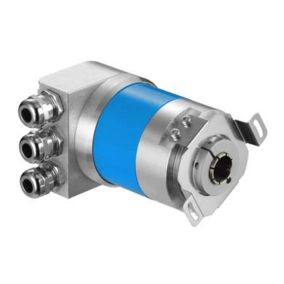
Connecting the encoder 12.6 Pin allocation 12.6.1 Bus connector with PG screw fittings In order to connect the bus lines and the supply, the bus connector must be removed. For this purpose, the three screws on the rear of the bus connector have to be unscrewed. The terminal strip described below becomes accessible. -
Page 53: Bus Connector With 5-Pole Micro Circular Plug Connectors
Connecting the encoder 12.6.2 Bus connector with 5-pole micro circular plug connectors Bus connectors of the type BC 6 SRx CO have M 12 circular plug connectors (5-pin micro style). In the case of this device type, it is not necessary for the bus connector to be unscrewed completely from the complete device in order to connect the bus and supply lines. -
Page 54: Commissioning
Commissioning Commissioning Before the encoder is switched on, the following settings must have been made: · Node ID · Baud rate · Bus terminating resistors The procedure for these settings is described in the chapter on “Connecting the encoder”. 13.1 Switch on encoder After applying the supply voltage, the encoder runs through an initialization phase and then changes automatically to the “pre-operational”... -
Page 55: Configure Encoder
Commissioning 13.2 Configure encoder If any configuration of objects in the encoder is needed, it is recommended to carry out this configuration in the “pre-operational” state. In this state, only the SDO connections are active, PDO connections become active only in the “operational” state. This means that the bus activity of the encoder is low in the “pre- operational”... -
Page 56: Write All Objects Into Eeprom
Commissioning The encoder replies with the following Initiate Download Response to the Master: SDO-ID Command Index Sub- 4-byte data index 11 bit Byte 0 Byte 1 Byte 2 Byte 3 Byte 4 Byte 5 Byte 6 Byte 7 COB-ID reserved SDO(tx) 13.2.3 Write all objects into EEPROM... -
Page 57: Eds File
Commissioning The Master sends the following Initiate Download Request to the encoder. SDO-ID Command Index Sub- 4-byte data index 11 bit Byte 0 Byte 1 Byte 2 Byte 3 Byte 4 Byte 5 Byte 6 Byte 7 COB-ID SDO(rx) ASCII l ASCII o ASCII a ASCII d... -
Page 58: Dimensional Drawing
Dimensional drawing Dimensional drawing ATM60-C4H13X13 (with face mount flange) ATM60-C1H13X13 (with servo flange) ATM60-CAH13X13 (with blind hollow shaft) Contact for stator coupling ATM60-Cxx 03/2007... - Page 59 Dimensional drawing Bus connector BC 6 with 5-pole micro circular plug-in connectors Bus connector BC 6 with PG for cable connection General view for bus connector ATM60-Cxx 03/2007...
-
Page 60: Scope Of Supply
Scope of supply Scope of supply ATM60-Cxx without cable or mating connector. Floppy disk with the EDS file. This file contains device-specific features of the ATM60-Cxx and can be read by a configuration tool. Commissioning instructions for ATM60-Cxx. Note Further literature: CANopen - Communications profile DS 301 V 4.0 CANopen - Device profile DS 406 V 2.0, profile for encoders Addresses:... - Page 61 Ordering information Ordering example ATM60-CAH13X13 : ATM60 with blind hollow shaft and CANopen interface SPZ-010-AD-A: Shaft insert for blind hollow shaft, 10 mm AD-ATM60-KR3CO: Bus connector, radial, cable outlet with 3 PG for CANopen interface. ATM60-Cxx 03/2007...
-
Page 62: Notes
Notes Notes ATM60-Cxx 03/2007... - Page 63 Notes ATM60-Cxx 03/2007...
- Page 64 N e d e r l a n d s Phone +31 (0)30 229 25 44 www.sick.com E-Mail info@sick.nl SICK AG • Industrial Sensors • Waldkirch • Germany • www.sick.com SICK STEGMANN GmbH • Donaueschingen • Germany • www.sick-stegmann.de...
Need help?
Do you have a question about the ATM 60-C Series and is the answer not in the manual?
Questions and answers