
Related Manuals for Fukuda Denshi IB-7300


Summary of Contents for Fukuda Denshi IB-7300
- Page 1 Service Manual Before setting up/maintenance, please read this service manual carefully. Keep this manual where it can be always referred to.
- Page 2 • The company and product names used in this manual are trademarks or registered trademarks. • If this manual has pages missing or out of order, contact Fukuda Denshi for replacement. • Only physician or persons instructed by physicians are allowed to use the equipment.
- Page 3 If you have any comment or request on usability, viewability, readability, or if you notice anything hard to understand on this service manual, please inform it to us. Development & Production Support Dept. Fukuda Denshi Co., Ltd. 2-35-8 Hongo Bunkyo-ku, Tokyo 113-8420 Japan Received by...
- Page 4 Preface Thank you for purchasing this product. Before using this product, read the following precautions to make sure the product is used correctly and safely. ・・・・・・・・・・・・・・・・・・・・・・・・・・・・・・・・・・・・・・・・・・・・・・・・ Safety Precautions ・・・・・・・・・・・・・・・・・・・・・・・・・・ Warnings and Symbols Used in this Manual ・・・・・・・・・・・・・・・・・・・・・・・・・・・・・・・ Precautions When Using This Manual ・・・・・・・・...
-
Page 5: Safety Precautions
Safety Precautions Read the “Safety Precautions” thoroughly before use to ensure correct and safe use of the product. Be sure to follow the precautions indicated below, as these are important messages related to safety. Warnings and Symbols Used in this Manual The following is an explanation of the various warnings and symbols used in this service manual. -
Page 6: Precautions When Using This Manual
Precautions When Using This Manual Be sure to follow the precautions indicated below when using this manual. Do not remodel the electronic medical equipment. D A N G E R Doing so may compromise the safety of the equipment and endanger the patient and operator. -
Page 7: Precautions For Safe Operation Of Medical Electrical Equipment
Precautions for Safe Operation of Medical Electrical Equipment Read the following precautions thoroughly to correctly operate the device. Users should have a thorough knowledge of the operation before using this system. Pay attention to the following when installing and storing the equipment. -
Page 8: Precautions Mentioned In The Manual
Precautions Mentioned in the Manual The precautions mentioned in the text are listed below. Before performing the task concerned, read the instructions carefully. Take care to avoid short-circuiting when checking the power unit, etc. Be sure to turn OFF the power and remove the plug from the outlet before checking the power supply fuse. -
Page 9: Precautions About This Device
Even a small potential difference may result in electric shock to the patient and the operator. Use the trolley only with the equipment specified by Fukuda Denshi. Otherwise, the monitor and trolley may fall down, resulting in injury or damage to the monitor. -
Page 10: Electromagnetic Compatibility
Electromagnetic Compatibility The performance of this device under electromagnetic environment complies with IEC/EN60601-1-2 (2001). Precautions for Safe Operation under Electromagnetic Influence If any sorts of electromagnetic wave, magnetic field, or static electricity exist around the device, noise interference or malfunction of the device may occur. -
Page 11: Compliance To The Electromagnetic Emissions
Compliance to the Electromagnetic Emissions The DS-7300 system is intended for use in the electromagnetic environment specified below. Emissions Test Compliance Electromagnetic Environment - Guidance The equipment uses RF energy that is necessary for the RF Emissions internal functioning of the equipment itself. Therefore, its Group 1 CISPR 11 RF emissions are very low and are not likely to cause any... - Page 12 Compliance to the Electromagnetic Immunity (2) The DS-7300 system is intended for use in the electromagnetic environment specified below. It should be assured that the DS-7300 system is used in such an environment. IEC60601-1-2 Compliance Electromagnetic Environment - Immunity Test Test Level Level Guidance...
- Page 13 Recommended Separation Distances between Portable and Mobile RF Communications Equipment and the DS-7300 System The DS-7300 system is intended for use in an environment in which radiated RF disturbances are controlled. The electromagnetic interference can be prevented by maintaining a minimum distance between portable and mobile RF communications equipment (transmitters) and the DS-7300 system as recommended below, according to the maximum output power of the communications equipment.
- Page 14 CAUTION FEDERAL LAW RESTRICTS THIS DEVICE TO SALE BY OR ON THE ORDER OF A PHYSICIAN. This page is only for the USA.
- Page 15 Blank Page...
-
Page 16: Table Of Contents
Contents The service manual contains technical data relating to the IB-7300 Input Box and has been prepared as an aid to setup and troubleshooting. The manual is for the use of our service representatives and specialist engineers and includes instructions on how to change the periodical replacement parts of the IB-7300 Input Box. -
Page 17: Chapter 1 General Description
Parameter Module Types ・・・・・・・・・・・・・・・・・・・・・・・・・・・・・・・・・・ Names of Parts and Their Functions ・・・・・・・・・・・・・・・・・・・・・・・・・・・・・・・・・・・・・・・・・・・・・・・・・・・・・・・ Front Side ・・・・・・・・・・・・・・・・・・・・・・・・・・・・・・・・・・・・・・・・・・・・・・・・・・・・・・・ Rear Side Chapter 2 Specification ・・・・・・・・・・・・・・・・・・・・・・・・・ IB-7300 Input Box Specification / Performance ・・・・・・・・・・・・・・・・・・・・・・・・・・・・・・・・・・・・・・・・・・・・・・・・・・・・・・・ Specification ・・・・・・・・・・・・・・・・・・・・・・・・・・・・・・・・・・・・・・・・・・・・・・・・・・・・・・・ Performance ・・・・・・・・・・・・・・・・・・・・・・・・・・・・・・・ HB-500 Invasive Blood Pressure Module ・・・・・・・・・・・・・・・・・・・・・・・・・・・・・・・・・・・・・・・・・・・・・・・・・・ HC-500 CO Module ・・・・・・・・・・・・・・・・・・・・・・・・・・・・・・・・・・・・・・・・... -
Page 18: Chapter 3 Connection Of Each Part
Connection of Each Part ・・・・・・・・・・・・・ Attaching the Super Module and Input Box (Using OAO-02A) ・・・・・・・・・・・・・・・・・・・・・・・・・・・・・ To Fix the IB-7300 on the Super Module ・・・・・・・・・・・・・・・・・・・・・・・・・・・・・ To Fix the Super Module on the IB-7300 ・・・・・・・・・・・・ Fixing the Super Module and Input Box to a Table (Using OAO-07A) ・・・・・・・... -
Page 19: Chapter 6 Spare Parts List
・・・・・・・・・・・・・・・・・・・・・・・・・・・・・・・・・・・・・・・・・・・・・・・・・・・・・・ Dsub Cover ・・・・・・・・・・・・・・・・・・・・・・・・・・・・・・・・・・・・・・・・・・・・・・・・・・・・・ Filter Holder Chapter 7 Assembling and Disassembling ・・・・・・・・・・・・・・・・・・・・・・・・・・・・・・ Main Unit Assembly Drawing 410-2905 ・・・・・・・・・・・・・・・・・・・・・・・・・・・ Assembling and Disassembling the IB-7300 ・・・・・・・・・・・・・・・・・・・・・・・・・・・・・・・・・・・・・・・・・・・・・・・・・・・・ Tool Required ・・・・・・・・・・・・・・・・・・・・・・・・・・・・・・・・・・・・・ Assembling and Disassembling ・・・・・・・・・・・・・・・・・・・・・・・・・・・・・・・・・ External Appearance (1) 410-2906 7-13 ・・・・・・・・・・・・・・・・・・・・・・・・・・・・・・・・・ External Appearance (2) -
Page 20: Chapter 9 Maintenance
Test Menu ・・・・・・・・・・・・・・・・・・・・・・・・・・・・・・・・・・・・・・・・・・・ To Display the Test Menu ・・・・・・・・・・・・・・・・・・・・・・・・・・・・・・・・・・・・・・・・・・・・・・・・・・・ Test Menu Items ・・・・・・・・・・・・・・・・・・・・・・・・・・・・・・・・・・・・・・・・・・・・ Details of the Test Menu ・・・・・・・・・・・・・・・・・・・・・・・・・・・・・・・・・・・・・・・ MAINTENANCE(IB-7300) ・・・・・ MAINTENANCE(IB-7300)- Memory Operation and Performance ・・・・・・・・・・・・・・・・・・・・・・・・・・・・・ MAINTENANCE(IB-7300)- EEPROM ・・・・・・・・・・・・・・・・・・・・・・・・・・・・・・・・・・・・・ Module Install (Program Install) Storage 9-9 ・・・・・・・・・・・・・・・・・・・・・・・・・・・・・・・・・・・・・・・・・・・・・・・・・・・・・・・・・・・ Storage Cleaning 9-10 ・・・・・・・・・・・・・・・・・・・・・・・・・・・・・・・・・・・・・・・・・・・・・・・・・・・・・・・・・... - Page 21 Blank Page xviii...
-
Page 22: General Description
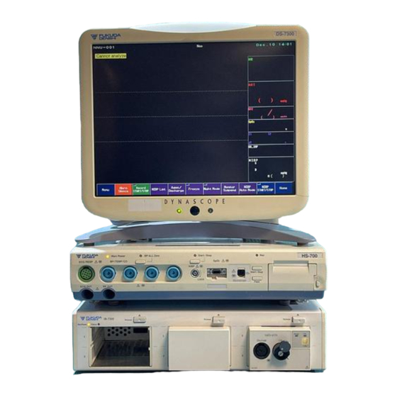
Chapter 1 General Description This chapter provides an overview of the DS-7300 system. ・・・・・・・・・・・・・・・・・・・・・・・・・・・・・・・・・・・・・・・・・・・・・・ General Description ・・・・・・・・・・・・・・・・・・・・・・・・・・・・・・・・・・・・・・・・・・・・・・・・・・・・・・ Features ・・・・・・・・・・・・・・・・・・・・・・・・・・・・・・・・・・・・・・・・ Parameter Module Types ・・・・・・・・・・・・・・・・・・・・・・・・・・・・・・・ Names of Parts and Their Functions ・・・・・・・・・・・・・・・・・・・・・・・・・・・・・・・・・・・・・・・・・・・・・・・・・・ Front Side ・・・・・・・・・・・・・・・・・・・・・・・・・・・・・・・・・・・・・・・・・・・・・・・・・・ Rear Side -... - Page 23 General Description The IB-7300 Input Box is designed to be used with the DS-7000 series bedside monitor and allows to extend the monitoring parameters using the modules. The parameter modules can be used in any combination by inserting to the input box.
-
Page 24: Parameter Module Types
Parameter Module Types The following are the parameter modules that can be used with the IB-7300 Input Box. No. of Used Model Name Description Slots Up to four (4) HB-500 can be used. HB-500 Invasive Blood If the same BP channel is measured by the... -
Page 25: Names Of Parts And Their Functions
4. Fuse Holder: Fuses are stored in here. 5. Power Supply Switch: Turns ON/OFF the power. Turning OFF the LC-7315T Display Unit will also turn OFF the IB-7300. 6. Cooling Fan: Inhale port for cooling fan. 7. Maintenance Cover: Used for maintenance. -
Page 26: Ib-7300 Input Box Specification / Performance Specification Performance
Chapter 2 Specification ・・・・・・・・・・・・・・・・・・・・・・ IB-7300 Input Box Specification / Performance ・・・・・・・・・・・・・・・・・・・・・・・・・・・・・・・・・・・・・・・・・・・・・・・・・・・ Specification ・・・・・・・・・・・・・・・・・・・・・・・・・・・・・・・・・・・・・・・・・・・・・・・・・・・ Performance ・・・・・・・・・・・・・・・・・・・・・・・・・・・ HB-500 Invasive Blood Pressure Module ・・・・・・・・・・・・・・・・・・・・・・・・・・・・・・・・・・・・・・・・・・・・・・・ HC-500 CO Module ・・・・・・・・・・・・・・・・・・・・・・・・・・・・・・・・・・・・・ HC-530 tcpO / tcpCO Module ・・・・・・・・・・・・・・・・・・・・・・・・・・・・・・・・・・・・・・・・・・・・・・・・・・・・・・・・ Unit ・・・・・・・・・・・・・・・・・・・・・・・・・・・・・・・・・・・・・・・・ TCC3 Calibration Unit ・・・・・・・・・・・・・・・・・・・・・・・・ E5280 Combined tcpO... - Page 27 IB-7300 Input Box Specification / Performance Specification Size 380 (W) ± 10mm x 230 (D) ± 10mm x 90 (H) ± 5mm (not including the protrusion) Weight 4.5 ± 0.5kg (not including the accessory) Environmental Condition : 10 ∼ 40 ° C Operating Temperature : 30 ∼...
- Page 28 Connector Module LAN Connector : Connects to DSC-7300 Main Unit or to HS-700 Series Super Module. Serial Connector : Connects to specified equipment. IB-7300 ↔ Super Module Communication Communication System : Ethernet Communication Rate : 100Mbps IB-7300 ↔ DSC-7300 Communication...
-
Page 29: Hb-500 Invasive Blood Pressure Module
HB-500 Invasive Blood Pressure Module Size 90.0(W) × 150.0(D) × 30.0(H) mm (approximate) Weight 300 g Module slot 1 slot(when inserted into IB-7300 the input box) Environmental Conditions Operating Temperature :10 ~ 40 ° C :30 ~ 85% (No Dew Condensation) Operating Humidity :700~1060hPa Operating Atmospheric Pressure :... - Page 30 Invasive Blood Pressure Transducer Sensitivity :5 µ V/V/mmHg Measurement Range : − 50~300mmHg Frequency Response :DC~ 6Hz DC~ 8Hz DC~12Hz DC~40Hz :±2% of full scale, or within±1mmHg Accuracy Zero Balance Range :±150mmHg(auto zero adjustment is done with key switch) Number of Channels :2 -...
-
Page 31: Co Module
90.0(W) × 150.0(D) × 30.0(H) mm (approximate) Weight 300 g Module slot 1 slot(when inserted into IB-7300 the input box) Environmental Conditions Operating Temperature :10 ∼ 40 ° C (HC-500) 15 ∼ 38 ° C (Capnostat sensor) :30 ∼ 85% (No Dew Condensation) Operating Humidity :700~1060hPa... - Page 32 :Infrared solid state sensor Method ® Capnostat ΙΙΙ :Respironics Novametrix Sensor Model :End-tidal CO (EtCO ), Inspired CO (InspCO ), Respiration Measured Parameters :CO :0 ~ 99mmHg Measurement Range :0 ~ 150Bpm Respiration Measurement Accuracy :CO : 0 ~ 40 mmHg, ±2mmHg 41 ~ 99 mmHg, ±5% :±1Bpm Respiration...
-
Page 33: Hc-530 Tcpo
* Protruding parts of the device are not included. Weight 300 g Module Slot 2 slots (when inserted into the IB-7300 input box) Environmental Requirements Operating Temperature :10 ~ 40 ° C :30 ~ 85% (No Dew Condensation) Operating Humidity :700~1060hPa... -
Page 34: Tcc3 Calibration Unit
Pressure of gas source :max. 2000kPa :8.0 ± 2.0ml/min Gas outflow :Selectable between 5, 10, 15, 20 and 50 minutes. Automatic shut-off For modification contact your nearest Fukuda Denshi representative. :120.0(W) × 230.0(D) × 80.0(H) Size(mm) E5280 Combined tcpO /pCO... -
Page 35: Hf-500 Cardiac Output Module
HF-500 Cardiac Output Module Size 90.0(W) × 150.0(D) × 30.0(H) mm (approximate) Weight 300 g Module slot 1 slot(when inserted into IB-7300 input box) Environmental Conditions Operating Temperature :10 ~ 40 ° C :30 ~ 85% (No Dew Condensation) Operating Humidity :700~1060hPa Operating Atmospheric Pressure :-10 ~ 60 °... - Page 36 Cardiac Output :Thermodilution method Method Tb measurement :Measured via thermodilution catheter. Ti measurement :Measured via separate injectate probe, or through In-line sensor in catheter system. If not measured, calculations are performed assuming 0 ° C for iced and 24 ° C for room temperatures. Measurement Range :CO :0.1 ~ 20 L/min Tb :17 ~ 45 °...
-
Page 37: Hr-500 Recorder Module
HR-500 Recorder Module Size 90.0(W) × 150.0(D) × 60.5(H) mm Weight 650 g Module slot 2 slot(when inserted into IB-7300 the input box) Environmental Characteristics Operating Temp 10 ~ 40 °C Operating Humidity 30 ~ 85 %, no dew condensation :700~1060hPa... -
Page 38: Accessories And Optional Accessories
【Accessories】 CS-18 Power Supply Cable: Qty.1 CS-24 Power Supply Cable: Qty.1 (for USA) CJ-732A Module Connection Cable (0.3m): Qty. 1 Operation Manual: Qty. 1 Usable Module Software Version for the IB-7300: Qty. 1 【Optional Accessories】 Item Model Type Description Ground Cable... -
Page 39: Co Module
HC-500 CO Module 【Accessories】 Operation Manual 【Optional Accessories】 Item Model Type Description ® CAPNOSTAT 6467-00 Airway Adapter (for adult) 6383-01 Airway Adapter (for neonate) 6384-01 Disposable Airway Adapter (for adult) 6663-01 Airway Adapter (for adult) 6383-00 Qty. 10 Airway Adapter (for neonate) 6384-00 Qty. -
Page 40: Connection Of Each Part
Connection of Each Part ・・・・・・・・ Attaching the Super Module and Input Box (Using OAO-02A) ・・・・・・・・・・・・・・・・・・・・・・・ To Fix the IB-7300 on the Super Module ・・・・・・・・・・・・・・・・・・・・・・・ To Fix the Super Module on the IB-7300 ・・・・・・・・・ Fixing the Super Module and Input Box to a Table (Using OAO-07A) ・・・... -
Page 41: Attaching The Super Module And Input Box (Using Oao-02A)
Plate L Rubber Support Screw B Align the front side of the IB-7300 to the line position on the Super Module and attach to the opening on the Base R and L. Push to the front until it locks. Front Side... -
Page 42: To Fix The Super Module On The Ib-7300
To Fix the Super Module on the IB-7300 Using the same procedure as above, fix on the Plate R and L to the bottom of the Super Module, and Base R and L to the top of the IB-7300. Super Module IB-7300 -... -
Page 43: Fixing The Super Module And Input Box To A Table (Using Oao-07A)
Fixing the Super Module and Input Box to a Table (Using OAO-07A) The Super Module and Input Box can be fixed to a table using the HS-700 mounting bracket (OAO-07A). The instructions below are for mounting the Input Box on top of the Super Module. The positions can be reversed. - Page 44 Be sure to tighten the screws securely to prevent the equipment from falling off. Fix the Input Box to the top of the Super Module. Use the binding screws to fix bracket A to the bottom of the IB-7300 and bracket B to the top of the Super Module.
- Page 45 Fix in place with the four screws provided. Screw (M3x8) (4) (provided) -...
-
Page 46: Connecting The Input Box, Dsc-7300 Main Unit, And Super Module
Input Box and Module Communication Connector on the DSC-7300. Using the CJ-732 Module Connection Cable, connect the “2 MODULE” connector on the Input Box and Main Unit Communication Connector on the Super Module. DSC-7300 Main Unit IB-7300 Input Box 1 DYNASCOPE Connector 2 MODULE Connector HS-700 series Super Module -... -
Page 47: Installation / Removal Of The Parameter Modules
Installation / Removal of the Parameter Modules Insert the parameter module into the slot. Maximum of 6 parameter modules can be inserted to one input box. Do not insert unspecified modules into the Input Box. Otherwise, the C A U T I O N equipment may be damaged, and safety cannot be ensured. -
Page 48: Connecting The Power Supply Cable
Connecting the Power Supply Cable Connect the Input Box to the AC power source. Connect the accessory power cable (CS-18 or CS-24) to the hospital grade outlet with ground terminal. Power Supply Connector CS-18 When the power cable is connected and the power supply switch is turned ON, the main power supply indicator on the front side will light to notify that the AC power is supplied. -
Page 49: Turning On The Power
Turning ON the Power First, turn ON the power switch of the main unit, Super Module, and Input Box. Then, turn ON the power switch of the display unit. The screen will be displayed, and monitoring will start. The power supply LED on the input box will light in green. Display Unit Main Unit Super Module... - Page 50 Chapter 4 Operations ・・・・・・・・・・・・・・・・・・・・・・・・・・・・・・・・・・・・・・・・・ IB-7300 Internal Structure ・・・・・・・・・・・・・・・・・・・・・・・・・・・・・・・・・・・・・・・・・・・・・・・ IB-7300 Structure ・・・・・・・・・・・・・・ IB-7300IB-7300 Board and Unit Configuration Diagram ・・・・・・・・・・・・・・・・・・・・・・・・・・・・・・・・・・・・・・・ Explanation of Each Block ・・・・・・・・・・・・・・・・・・・・・・・・・・・・・・・・・・・・・・・・・ Explanation of the Boards ・・・・・・・・・・・・・・・・・・・・・・・・・・・・・・・・・・・・・・・・・・・ CPU Board (IB7CPU) ・・・・・・・・・・・・・・・・・・・・・・・・・・・・・・・・・・・・・・・・・・・・・・ Block Diagram ・・・・・・・・・・・・・・・・・・・・・・・・・・・・・・・・・・・・・・・・・ Operation Overview ・・・・・・・・・・・・・・・・・・・・・・・・・・・・・・・・・・・・・・ DIPDIP Switch Settings ・・・・・・・・・・・・・・・・・・・・・・・・・・・・・・・・・・・・・・・...
-
Page 51: Ib-7300 Internal Structure
Removing or replacing the printed circuit board with the power ON may cause malfunction or damage. IB-7300 Structure The IB-7300 is composed of the boards and units shown in the diagram below. IB-7300 IB-7300 MODULE Mother Board IB7MBD IB-7300 CPU Board... - Page 52 IB-7300IB-7300 Board and Unit Configuration Diagram Serial Port CF Card Slot Option MODULE SLOT-1 Option MODULE SLOT-2 Service Switch Status LED Option MODULE SLOT-3 MODULE Mother Board CPU Board CONNECTOR MODULE Option MODULE Board IB7MBD IB7CPU SLOT-4 IB7CNT DYNASCOPE Option MODULE SLOT-5 Cooling FAN Option MODULE...
-
Page 53: Explanation Of Each Block
Explanation of Each Block 1. Power Supply Unit ・ Input power supply AC100-240V 50/60Hz ・ The commercial power source from the AC inlet is input to the power supply unit via the AC inlet fuse and AC power switch. ・ The power supply is converted to DC24V by the power supply unit and input to the CPU board. 2. -
Page 54: Explanation Of The Boards
Explanation of the Boards CPU Board (IB7CPU) Block Diagram The CPU board has various interfaces centering on the 32bit-RISC CPU. It performs signal processing, communication processing, display processing and control. MAIN-CPU Flash Memory Module-LAN Memory CF Card Driver EEPROM Main Rotary SW Gate Array DIP SW... -
Page 55: Operation Overview
・ The IB-7300 power supply is controlled by a signal inside the module-LAN cable. ・ Turning the DS-7300 ON and OFF will also turn the IB-7300 ON and OFF. ・ To turn the IB-7300 ON independently such as for repairs, set DIP-SW-5 to ON. -
Page 56: Rotary Switch Settings
DIP Switch Settings Default Setting Description (when ON) Domestic Export Not used (Reserved function) Not used (Reserved function) Not used (Reserved function) Not used (Reserved function) Forced power supply ON Linked to monitor Power failure buzzer OFF Buzzer ON Not used (Reserved function) Forced installation and EEPROM data writing Rotary Switch Settings... -
Page 57: Connectors
Connectors Power Supply Connector (CN1) Signal Name Remarks Signal Level +24V Main power supply input(+24V) +24V Main power supply input(+24V) +24V Main power supply input(+24V) Main power supply input(GND) Main power supply input(GND) Main power supply input(GND) Fan Connector (CN2) Signal Name Remarks Signal Level... - Page 58 No wire connection No wire connection No wire connection No wire connection No wire connection No wire connection +3.3V Power supply Power supply POW_CNT IB-7300 power supply control 3.3V DYNASCOPE Communication: LINK_LED0 3.3V LINK_LED Module Communication: LINK_LED1 3.3V LINK_LED for transmission...
- Page 59 Signal Name Remarks Signal Level Circuit Power Supply SELMJ6 Module Identification Slot-6 TTL 5V 5000 Module Communication: SCA RXD TTL 5V Receive SELMJ5 Module Identification Slot-5 TTL 5V 5000 Module Communication: SCA TXD TTL 5V Transmit SELMJ4 Module Identification Slot-4 TTL 5V LOAD6 Module Selection Slot-6...
- Page 60 Signal Name Remarks Signal Level Signal/Power Supply GND Signal/Power Supply GND Signal/Power Supply GND Signal/Power Supply GND Signal/Power Supply GND -...
-
Page 61: Module Mother Board (Ib7Mbd)
Module Mother Board (IB7MBD) Block Diagram The Module Mother Board acts as an interface with the option modules. MODULE Slot-1 Interface MODULE Slot-2 Interface MODULE Slot-3 Interface BUFFER MODULE Slot-4 Interface MODULE Slot-5 Interface MODULE Slot-6 Interface Operation Overview MODULE Slot-x Interface ・... -
Page 62: Board Fuse Settings
Board Fuse Settings Name Description Setting Not provided 24V Slot-1 1A Polyswitch Not provided 24V Slot-2 1A Polyswitch Not provided 24V Slot-3 1A Polyswitch Not provided 24V Slot-4 1A Polyswitch Not provided 24V Slot-5 1A Polyswitch Not provided 24V Slot-6 1A Polyswitch 5V Slot-1 0.2A Polyswitch... - Page 63 CPU Interface Connector (CN7) Signal Name Remarks Signal Level +24V Module Power Supply +24V Module Power Supply +24V Module Power Supply +24V Module Power Supply +24V Module Power Supply +24V Module Power Supply Circuit Power Supply Circuit Power Supply Circuit Power Supply Circuit Power Supply SELMJ6 Module Identification Slot-6...
- Page 64 Signal Name Remarks Signal Level RESET5 7000 Module Reset Slot-5 TTL 5V RESET1 7000 Module Reset Slot-1 TTL 5V RESET4 7000 Module Reset Slot-4 TTL 5V BD_VER0 Board Version bit-0 BD_VER1 Board Version bit-1 BD_VER2 Board Version bit-2 BD_VER3 Board Version bit-3 Signal/Power Supply GND Signal/Power Supply GND Signal/Power Supply GND...
- Page 65 Operation Overview Power-ON Control ・ In normal use, the IB-7300 is turned ON and OFF by linkage with the DS-7300. ・ The Power-ON control isolates the power ON/OFF signal from the DS-7300 by the photocoupler and transmits it to the IB7CPU.
- Page 66 Power Control Input L from DS-7300 POW1_L (When powering is controlled by 5-10V DS-7300) No Connection SHIELD Shield Transmit + IB-7300 ⇒ DS-7300 Ethernet Transmit - IB-7300 ⇒ DS-7300 Ethernet Receive + DS-7300 ⇒ IB-7300 Ethernet Receive - DS-7300 ⇒ IB-7300 Ethernet...
- Page 67 No wire connection No wire connection No wire connection No wire connection No wire connection No wire connection No wire connection +3.3V Power Supply Power Supply POW_CNT IB-7300 Power Control 3.3V DYNASCOPE LINK_LED0 3.3V Communication:LINK_LED Module Communication: LINK_LED1 3.3V Transmit LINK_LED -...
- Page 68 ・ When the cable is inserted correctly and communication starts: Green ・ When communication cannot be established: OFF Status LED (Inside maintenance cover) This LED indicates the status of the IB-7300. ・ For details of the display content, see “Maintenance: 7-Segment LED Display”. -...
- Page 69 Power Control Input L from DS-7300 POW1_L (When powering is controlled by 5-10V DS-7300) No Connection SHIELD Shield Transmit + IB-7300 ⇒ DS-7300 Ethernet Transmit - IB-7300 ⇒ DS-7300 Ethernet Receive + DS-7300 ⇒ IB-7300 Ethernet Receive - DS-7300 ⇒ IB-7300 Ethernet...
- Page 70 Power Control Output L to HS-700 POW_L (When powering is controlled by 5-10V DS-7300) No Connection SHIELD Shield Receive + HS-700 ⇒ IB-7300 Ethernet Receive - HS-700 ⇒ IB-7300 Ethernet Transmit + IB-7300 ⇒ HS-700 Ethernet Transmit - IB-7300 ⇒ HS-700 Ethernet...
- Page 71 Blank Page -...
- Page 72 Chapter 5 Wiring Diagram ・・・・・・・・・・・・・・・・・・・・・・・・・・・・・・・・・・・・・・・・・・・・・・・・・・ Wiring Diagram ・・・・・・・・・・・・・・・・・・・・・・・・・・・・・・・・・・・・・・・・・・・・・・・・・・・・・ DC24V Cable ・・・・・・・・・・・・・・・・・・・・・・・・・・・・・・・・・・・・・・・・・・・・・・・・・・・・・・・・ Fan Cable ・・・・・・・・・・・・・・・・・・・・・・・・・・・・・・・・・・・・・・・・・・・・・・・・・・・ AC PWR Cable ・・・・・・・・・・・・・・・・・・・・・・・・・・・・・・・・・・・・・・・・・・・ Ground Terminal Cable ・・・・・・・・・・・・・・・・・・・・・・・・・・・・・・・・・・・・ Wiring Diagram in the Inlet Unit -...
- Page 73 Wiring Diagram -...
- Page 74 DC24V Cable -...
- Page 75 Fan Cable -...
- Page 76 AC PWR Cable -...
- Page 77 Ground Terminal Cable -...
- Page 78 Wiring Diagram in the Inlet Unit -...
- Page 79 BlankPage -...
- Page 80 Chapter 6 Spare Parts List ・・・・・・・・・・・・・・・・・・・・・・・・・・・・・・・・・・・・・・・・・・・・・・・・・ Electrical Parts ・・・・・・・・・・・・・・・・・・・・・・・・・・・・・・・・・・・・・・・・・・・・・・・・・・・・ Air Filter ・・・・・・・・・・・・・・・・・・・・・・・・・・・・・・・・・・・・・・・・・・・・・・・・・ Power Unit ・・・・・・・・・・・・・・・・・・・・・・・・・・・・・・・・・・・・・・・・・・・・・・・・・・・・・・・ Fuse ・・・・・・・・・・・・・・・・・・・・・・・・・・・・・・・・・・・・・・・・・・・・・・・・・ CPU Board ・・・・・・・・・・・・・・・・・・・・・・・・・・・・・・・・・・・・・・・・・・・・ Connector Board ・・・・・・・・・・・・・・・・・・・・・・・・・・・・・・・・・・・・・・・・ Module Mother Board ・・・・・・・・・・・・・・・・・・・・・・・・・・・・・・・・・・・・・・・・・・・・・・・・・・・・ Fan Unit ・・・・・・・・・・・・・・・・・・・・・・・・・・・・・・・・・・・・・・・・・・・・・・・・ AC Inlet Unit ・・・・・・・・・・・・・・・・・・・・・・・・・・・・・・・・・・・・・・・・・・・・・・ Internal Cables ・・・・・・・・・・・・・・・・・・・・・・・・・・・・・・・・・・・・・・・・・・・・・・・・ Structural Parts ・・・・・・・・・・・・・・・・・・・・・・・・・・・・・・・・・・・・・・・・・・・ Chassis Assembly ・・・・・・・・・・・・・・・・・・・・・・・・・・・・・・・・・・・・・・・・...
- Page 81 The power unit generates a DC power supply from a commercial AC power supply for use inside the equipment. Item: 9E1858 Model Standard: IB-7300 Power Unit Assembly Remarks: With DC output cable Fuse A primary protective device located in the AC inlet.
- Page 82 Internal Cables The following cables are used inside the IB-7300. DC24V Cable Fig. No.: G4E01874 Remarks: Connects the Power Board and CPU Board. FAN Cable Fig. No.: G4E01872 Remarks: The wire rod is direct-mounted on the fan unit. AC PWR Cable Fig.
- Page 83 Guide Assembly R This is the right-hand guide for inserting the module. (With lock plates) (Three guides) Guide Assembly L This is the left-hand guide for inserting the module. (Three guides) Film This is the insulation sheet for the mother board. Sponge 1 The conductive sponge (large) is attached to the unit cover and is in contact with the CPU board.
- Page 84 Chapter 7 Assembling and Disassembling ・・・・・・・・・・・・・・・・・・・・・・・・・・・ Main Unit Assembly Drawing 410-2905 ・・・・・・・・・・・・・・・・・・・・・・・・ Assembling and Disassembling the IB-7300 ・・・・・・・・・・・・・・・・・・・・・・・・・・・・・・・・・・・・・・・・・・・・・・・ Tool Required ・・・・・・・・・・・・・・・・・・・・・・・・・・・・・・・ Assembling and Disassembling ・・・・・・・・・・・・・・・・・・・・・・・・・・・・・・ External Appearance (1) 410-2906 7-13 ・・・・・・・・・・・・・・・・・・・・・・・・・・・・・・ External Appearance (2) 410-2907 7-14 ・・・・・・・・・・・・・・・・・・・・・・・・・・・・・・・・・・ Packing Instruction 410-2908 7-15 -...
-
Page 85: Main Unit Assembly Drawing 410-2905
Main Unit Assembly Drawing 410-2905 -... - Page 86 -...
-
Page 87: Assembling And Disassembling The Ib-7300
Check that no foreign objects are left inside the equipment Tool Required ・Phillips screwdriver (large) Assembling and Disassembling Follow the procedure below, taking care with the wiring. 1. Disassemble the IB-7300 main unit and rear cover. IB-7300 Main Unit: 9G7467 IB-7300 Rear Cover Unit: 9G7468 Binding Screw (M3x6) (5) - Page 88 2. Disassemble the main unit. When removing the cover assembly and insulating plate (cover), slide the cover to release the catch, as shown in the diagram, and then lift off. Cover Assembly, Insulating Plate (Cover) Binding Screw (M3x6) (4) Slide to release catch Support Catch...
- Page 89 4. Disassemble the main unit. IB-7300 IB7CPU BOARD ASSY :9E1854 W Sems Screw (L) (M3x6) (8) 5. Dismantle the main unit. Button Assy W Sems Screw (L) M3 × 5 (5) -...
- Page 90 6. Disassemble the main unit. Power Unit Assy: 9E1858 W Sems Screw (L) (M3x6) (3) Sems Screw (L) (M3x6) (2) IB-7300 IB7CNT Board Assy : 9E1855 Insulating Plate (Connector Card) W Sems Screw (L) M3 × 6 (2) Fan Unit Assy: 9E1857 7.
- Page 91 8. Disassemble the main unit. Slide the unit cover to release the Guide R and L catch, as shown in the diagram, and lift off. Unit Cover W Sems Screw (L) (M3x6) (4) (Sponge 1, 2, 3) Slide to release catch Guide R and L Catch 9.
- Page 92 10. Disassemble the main unit. Plate Bottom W Sems Screw (L) (M3x6) (10) Chassis Assy 11. Disassemble the front panel. Panel Corner (L) Front Panel Assy Panel Corner (R) W Sems Screw (L) (M3x6) (4) -...
- Page 93 12. Disassemble the button assembly. Remove the E-rings, shafts and springs in order. E-ring (6) (2 spare) Push Button: 6B8493 (3) P Spring C-148: 6B4950 (6) Shaft: 6B8494 (6) Hold Button 13. Disassemble the Guide R assembly. Guide R S Spring E-601: 6B8499 W Sems Screw (L) (M3x6) (2) Lock Plate Shelf Plate...
- Page 94 14. Dismantle the Guide L assembly. Guide L Angle Guide W Sems Screw (L) (M3x6) 15. Disassemble the power unit assembly. Inlet Assy: 9E1859 GND Mask Inside Panel: 5H5601 Power Supply W Sems Screw (L) (M3x6) (5) Insulating Plate PS 16.
- Page 95 17. Disassemble the rear cover unit. Dsub Cover Back Panel Assy 7-Segment LED Cover Binding Screw (M3x6) (3) Fan Filter: 6C5572 Filter Holder 18. To assemble, follow the procedures in Step 1 to 17 above in reverse order. After assembling, check operation of the equipment. To ensure safety, measure the ground leakage current and patient leakage current and perform a pressure test.
-
Page 96: External Appearance (1) 410-2906
External Appearance (1) 410-2906 -... -
Page 97: External Appearance (2) 410-2907
External Appearance (2) 410-2907 -... -
Page 98: Packing Instruction
Packing Instruction 410-2908 -... - Page 99 Blank Page -...
- Page 100 Chapter 8 Troubleshooting ・・・・・・・・・・・・・・・・・・・・・・・・・・・・・・・・・・・・・・・・・・ IB-7300 Troubleshooting ・・・・・・・・・・・・・・・・・・・・・・・・・・・・・・・・・・・・・・・・・・・・・ List of Display Codes ・・・・・・・・・・・・・・・・・・・・・・・・・・・・・・・・・・・・・・・・・ 7-segment LED Display ・・・・・・・・・・・・・・・・・・・・・・・・・・・・・・・・・・・・・・・・・・・・・・ Normal Startup ・・・・・・・・・・・・・・・・・・・・・・・・・・・・・・・・・・・ During Program Installation ・・・・・・・・・・・・・・・・・・・・・ During Program Installation From DS-7300 ・・・・・・・・・・・・・・・・・・・・・・・・・・・・・・・・・・・・・・・・・・・・・・ Front LED Display ・・・・・・・・・・・・・・・・・・・・・・・・・・・・・・・・・・・・・・ Memory Test Error Display ・・・・・・・・・・・・・・・・・・・・・・・・・・・・・・・・・・・・・・・・・・・・・・ LINK-LED Display...
-
Page 101: Ib-7300 Troubleshooting
Connect the DSC-7300 and HS-700 correctly using the module LAN cable. The LINK-LED on the back of the IB-7300 lights when connected correctly and communication is established. An error code is displayed on the 7-segment LED on the back of the IB-7300 and the equipment fails to operate. Cause: An internal error was detected. - Page 102 The DS-7300 and HS-700 are running an old program version. Solution: Update the DS-7300 and HS-700 program version to V03-01 or later. The “Check IB-7300 cooling fan” message is displayed on the monitor. Cause : The cooling fan is conjested reducing the cooling effect.
-
Page 103: List Of Display Codes
List of Display Codes The IB-7300 has LEDs and the following displays appear depending on the status. IB-7300 Rear Side 7-segment LED (Chip LED underneath) LINK-LED The 7-segment LED is inside the maintenance cover (7-segment cover). (See the rear cover unit drawing on page 7-12.) -
Page 104: 7-Segment Led Display
Code Meaning Description Shows the boot program version after the IB-7300 Startup IB-7300 is turned on. The display format is like “V01-01”. This error appears when an abnormality is detected in the 24V power supply voltage CPU Board Power supplied to the IB-7300 CPU. -
Page 105: During Program Installation
During Program Installation If an error occurs, the information is displayed on the 7-segment LED and installation stops. Code Meaning Description Install Process Initial Appears during the initial phase of installation, Phase such as writing of the installation program. Flash ROM Erase Appears when erasing the Flash ROM domain, Phase except the boot area and adjust data area. -
Page 106: During Program Installation From Ds-7300
During Program Installation From DS-7300 Code Meaning Description Appears while Flash ROM sector nn is being Installing processed. “nn” indicates the sector number Appears while sector nn is being written to the Flash Writing Flash ROM. “nn” indicates the sector number. -... -
Page 107: Front Led Display
Front LED Display Main Power LED Display LED Type Description Information Lights when the Input Box is turned ON and the Front LED Orange LC-7315T display unit is turned OFF (in standby (Main Power LED) mode) Front LED Lights when the DS-7300 system is turned ON (the Green (Main Power LED) LC-7315T display unit is turned ON) and operating. - Page 108 ・・・・・・・・・・・・・・・・・・・・・・・・・・・・・・・・・・・・・・・・・・・・・・・・・・・・・・・ Test Menu ・・・・・・・・・・・・・・・・・・・・・・・・・・・・・・・・・・・・・・・ To Display the Test Menu ・・・・・・・・・・・・・・・・・・・・・・・・・・・・・・・・・・・・・・・・・・・・・・・ Test Menu Items ・・・・・・・・・・・・・・・・・・・・・・・・・・・・・・・・・・・・・・・・・ Details of the Test Menu ・・・・・・・・・・・・・・・・・・・・・・・・・・・・・・・・・・ MAINTENANCE(IB-7300) MAINTENANCE(IB-7300)- Memory Operation and Performance 9-6 ・・・・・・・・・・・・・・・・・・・・・・・・ MAINTENANCE(IB-7300)- EEPROM ・・・・・・・・・・・・・・・・・・・・・・・・・・・・・・・ Module Install (Program Install) ・・・・・・・・・・・・・・・・・・・・・・・・・・・・・・・・・・・・・・・・・・・・・・・・・・・・・・・・・・ Storage ・・・・・・・・・・・・・・・・・・・・・・・・・・・・・・・・・・・・・・・・・・・・・・・・・・・・・・・ Storage ・・・・・・・・・・・・・・・・・・・・・・・・・・・・・・・・・・・・・・・・・・・・・・・・・・・・・・・...
-
Page 109: Dip Switch/Rotary Switch Setup
The DIP switch and rotary switch are located inside the maintenance cover (7-segment LED cover) on the back of the main unit. Rotary Switch DIP Switch IB-7300 DIP Switch Setup SW No. Default Description (When ON) Not used. (Reserved function) Not used. -
Page 110: Test Menu
The Test Menu screen differs according to the software version. Test Menu Items Module Install : This is used when installing the program in the IB-7300. Do not remove the CF card during installation. A separate module installation program CF card is required for each module. -
Page 111: Details Of The Test Menu
Details of the Test Menu MAINTENANCE(IB-7300) * LOG1 or LOG2 does not function if pressed. CPU A/D Data Allows checking of the data, such as the voltage read by the AD converter and the analog data, and whether the value range is normal (normal operation). - Page 112 SRAM CLEAR FACTOR (Not used) DIP SW ROTARY SW Displays the setting status of the DIP switch and rotary switch. PORT DATA Displays port data. (For development) BUS CONTROLER Displays the bus controller. (For development) SERIAL REGISTER Displays the serial register. (For development) RESET REGISTER Displays the reset register.
-
Page 113: Maintenance(Ib-7300)- Memory Operation And Performance
MAINTENANCE(IB-7300)- Memory Operation and Performance The following screen is displayed when the Memory Operation key (or Performance key) is pressed in the Maintenance (IB-7300) window. This screen is for development. Never operate from this screen as it may W A R N I N G cause malfunction. -
Page 114: Maintenance(Ib-7300)- Eeprom
MAINTENANCE(IB-7300)- EEPROM This screen is displayed when the EEPROM key is pressed in the Maintenance (IB-7300) window. The accumulative operating hours of representative modules are saved in the IB-7300, enabling them to be checked in this screen. To display the accumulative operating hours, press the title part (“IB-7300 N O T E EEPROM”) on the EEPROM (IB-7300) screen for more than 2 seconds. -
Page 115: Module Install (Program Install)
Module Install (Program Install) This is used to install the program for each module connected to the DS-7300. You are recommended to create a backup before installing the program C A U T I O N to prevent loss of data saved in the equipment. Do not turn off the equipment during installation. -
Page 116: Storage
Storage This section explains storage of the equipment. Storage Store in a place where the device will not be exposed to splashing water. Store in a place where the device will not be adversely affected by atmospheric pressure, temperature, humidity, ventilation, sunlight, dust or atmosphere containing salt or sulfur. Store in a level area where the device is not exposed to vibration and shock (including during transportation). -
Page 117: Cleaning
Cleaning This section explains cleaning of the equipment. Cleaning Clean the equipment and cables using tightly squeezed gauze or an absorbent cotton cloth dampened with alcohol or a neutral cleanser. Clean the equipment frequently so stains can be removed easily. To prevent injury, it is recommended to wear gloves when cleaning the equipment. - Page 118 Reattach the cooling fan cover. The air filter must be attached after cleaning/replacing. If the equipment is W A R N I N G used with the air filter detached, it will become faulty. -...
- Page 119 Blank Page -...
- Page 120 Maintenance Check 10-2 Daily Check ・・・・・・・・・・・・・・・・・・・・・・・・・・・・・・・・・・・・・・・・・・・・・・・ 10-2 Periodic Check 10-2 ・・・・・・・・・・・・・・・・・・・・・・・・・・・・・・・・・・・・・・・・・・・・・ ・・・・・・・・・・・・・・・・・・・・・・・・・・・・・・・・・・・・・・・・・・・・・・・・・・・・ Daily Check 10-3 Daily Check Procedure (IB-7300) ・・・・・・・・・・・・・・・・・・・・・・・・・・・・・・・・ 10-3 Daily Check List (IB-7300) 10-4 ・・・・・・・・・・・・・・・・・・・・・・・・・・・・・・・・・・・ Daily Check Procedure (Parameter Modules) ・・・・・・・・・・・・・・・・・・・・・ 10-5 Daily Check List (HR-500) ・・・・・・・・・・・・・・・・・・・・・・・・・・・・・・・・・・・ 10-6 Daily Check List (HB-500) ・・・・・・・・・・・・・・・・・・・・・・・・・・・・・・・・・・・...
- Page 121 Maintenance Check Periodic inspection must be performed. When reusing the device which was left unused for a while, always check that the device operates properly and safely before use. To ensure safety, reliability, and high performance, a “Daily Check” and “Periodic Inspection” must be performed.
- Page 122 Daily Check Daily Check Procedure (IB-7300) Check Item Check Procedure Criteria 1 Appearance, Accessories Appearance Visually check the exterior for No abnormality should be scratches, cracks, deformation, and found. rust. Installation Check whether the unit is installed on a The installation area must level surface.
- Page 123 Daily Check List (IB-7300) Daily Check List Inspected Date Inspected by Location Device Type IB-7300 Serial No. Date of Purchase Item Details Criteria Judgment Visually check the exterior for scratches, cracks, deformation, and No abnormality should be found. OK / NG Appearance rust.
- Page 124 Daily Check Procedure (Parameter Modules) The daily check lists for parameter modules that can be used with the IB-7300 are shown on the following pages. Daily checks should be performed referring to daily check procedures for the IB-7300. ・P10-6 Daily Check List (HR-500) ・P10-7 Daily Check List (HB-500)
- Page 125 Daily Check List (HR-500) Daily Check List Inspected Date Inspected by Location Device Type HR-500 Serial No. Date of Purchase Item Details Criteria Judgment Visually check for any damage, No abnormality. Appearance cracks, deformity, rust, etc. on the OK / NG outer enclosure.
- Page 126 Daily Check List (HB-500) Daily Check List Inspected Date Inspected by Location Device Type HB-500 Serial No. Date of Purchase Channel No. ch/ Item Details Criteria Judgment Make sure to check visually that flaws, OK / NG The defects shall not affect the Appearance cracks, deformation, and rust are not monitoring operation.
- Page 127 Daily Check List (HC-500) Daily Check List Inspected Date Inspected by Location Device Type HC-500 Serial No. Date of Purchase Item Details Criteria Judgment Make sure to check visually that flaws, OK / NG The defects shall not affect the Appearance cracks, deformation, and rust are not monitoring operation.
- Page 128 Daily Check List (HF-500) Daily Check List Inspected Date Inspected by Location Device Type HF-500 Serial No. Date of Purchase Item Details Criteria Judgment Make sure to check visually for flaws, OK / NG The defects shall not affect the Appearance cracks, deformation, and rust are not monitoring operation.
- Page 129 Daily Check List (HC-530) Daily Check List Inspected Date Inspected by Location Device Type HC-530 Serial No. Date of Purchase Item Details Criteria Judgment Visually check for any damage, OK / NG Appearance cracks, deformity, rust, etc. on the No abnormality. outer enclosure.
-
Page 130: Chapter 10 Periodic Check
Periodic Check Periodic Check (Whole biological information monitoring equipment) Introduction The periodic maintenance check is intended to check the medical equipment used daily, to prevent failures and accidents and to ensure safety and reliability. As these are general check procedures covering the whole monitoring equipment, perform the check procedure for the corresponded function of subject equipment. - Page 131 C A U T I O N The measurement device must be properly calibrated. Periodic Check Item The periodic check items are as follows. Check Item External Appearance Power Supply Part Display/Control/Record Respiration Temperature Non-invasive Blood Pressure Arterial Oxygen Saturation (SpO Invasive Blood Pressure Cardiac Output (CO) Carbon Dioxide Concentration (CO...
- Page 132 Check Item Check Procedure Criteria 2. Power Supply Part Main Power Supply Connect the power cable to Main power supply indicator Switch the outlet, and turn ON/OFF should light by AC power supply. the power switch. Standby Switch Turn ON/OFF the standby The home display should appear switch.
- Page 133 Check Item Check Procedure Criteria 4. ECG Input Measure input impedance by Should be 5MΩ or above. Impedance* comprehensive tester. Suppression With SG-2000, input 50Hz or 60Hz Should be 10mmp-p or below for Characteristic of 20Vr.m.s. signal, and measure standard sensitivity (sensitivity Common-Mode fluctuation of each lead.
- Page 134 Check Item Check Procedure Criteria 5. Respiration Respiration With comprehensive tester or reference The displayed amplitude Accuracy respiration signal generator, input should be within sinusoidal waveform of 0.5Hz with base 10mm±2mm. resistance of 1.5kΩ/1Ω change. Respiration Rate Input reference respiration signal to Error should be within Accuracy comprehensive tester or respiration...
- Page 135 Check Item Check Procedure Criteria 9. Invasive Blood Pressure BP Accuracy Input 0, 100, 200mmHg with Error should be within display comprehensive tester, and measure full scale (300mmHg) ±2% or the error between the displayed value ±1mmHg whichever larger. and input value. Pulse Detection Input 30, 120, 160bpm with Pulse rate error should be...
- Page 136 Check Item Check Procedure Criteria 13. Calibration Touch Panel Perform calibration when the Touch panel calibration value is stored display is largely displaced. in the display unit. Analog If measurement error of ECG, Calibration value of analog board is BP, TEMP, CO is large, stored in the CPU board.
- Page 137 Check Item Check Procedure Criteria 14. Electrical Safety Earth Leakage Measure the earth leakage current of Earth Leakage Current (NC) Current (NC) normal condition using the leakage Should be ≤0.1mA measurement jig. According to test procedure of IEC 60601-1 19. Earth Leakage Measure the earth leakage current of Earth Leakage Current...
- Page 138 Check Item Check Procedure Criteria 14. Electrical Safety (※) Perform the following check item as appropriate. Check these items when you have disassembled the equipment to check / replace the boards or units. Protective Ground Measure the protective ground continuity Should be 0.1Ω...
- Page 139 Periodic Check List Bedside Monitor Periodic Check Report Check Date Periodic Check Contract Delivery Date Location □Yes □No Customer Code Month Check Model Name Serial No.: Product Code Next Check Date Requested Acceptance Date Item Check Item Judge Check Item Judge Check Item Judge...
- Page 140 Periodic Check Procedure (Parameter Modules) The periodic check lists for parameter modules that can be used with the IB-7300 are shown on the following pages. Periodic checks should be performed referring to the periodic check procedures for the whole biological information monitoring equipment.
- Page 141 Periodic Check List (HR-500) Periodic Check List Item Inspection Method / Criteria Judgment Comment Should be stored in specified OK / NG 1. Operation Manual Consumables, location. Accessories 2. Recording Paper Remaining stock should be in OK / NG good condition. 1.
- Page 142 Periodic Check List (HB-500) Periodic Check List Item Inspection Method /Criteria Judgment Comment Check visually, and by cable OK / NG 1.Interface Cable Cables, conduction test Consumables, 2.Channel Identification Label Check storage conditions. OK / NG Accessories Should be stored in specified OK / NG 3.
- Page 143 Periodic Check List (HC-500) Periodic Check List Item Inspection Method / Criteria Judgment Comment 1.Capnostat Sensor Check visually damage, flaw OK / NG Cord 2.Airway Adapter Check storage conditions. OK / NG Accessories 3.Operation Manual Must be kept as specified. OK / NG Appearance 1.Flaws, Cracks, Deformation and...
- Page 144 Periodic Check List (HF-500) Periodic Check List Item Inspection Method / Criteria Judgment Comment 1.Interface Cable Check visually and conduct OK/NG Cord wiring test. Accessories 2.Operation Manual Must be kept as specified. OK/NG 1.Flaws, Cracks, Deformation and Must be free from damage. OK/NG Rust 2.Panel and Label...
- Page 145 Periodic Check List (HC-530) Periodic Check List Item Inspection Method / Criteria Judgment Comment 1. tcp Electrode No damage should be found. OK/NG Cords, Accessorie 2. Accessories for Electrode Check storage conditions. OK/NG 3. Operation Manual Must be kept as specified. OK/NG 1.
- Page 146 39-4, Hongo, 3-chome, Bunkyo-ku, Tokyo, Japan Phone:+81-3-3815-2121 Fax:+81-3-3814-1222 Printed in Japan 4R0021740 200706...
Need help?
Do you have a question about the IB-7300 and is the answer not in the manual?
Questions and answers