Table of Contents
Advertisement
Quick Links
Advertisement
Table of Contents

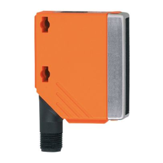
Summary of Contents for IFM Electronic efector 200 O5D15 Series
- Page 1 Operating instructions Optical distance sensor O5D15x...
-
Page 2: Table Of Contents
Contents 1 Preliminary note ���������������������������������������������������������������������������������������������������3 1�1 Symbols used ������������������������������������������������������������������������������������������������3 2 Safety instructions �����������������������������������������������������������������������������������������������3 3 Functions and features ����������������������������������������������������������������������������������������4 3�1 Applications ���������������������������������������������������������������������������������������������������4 4 Installation������������������������������������������������������������������������������������������������������������5 4�1 Installation conditions ������������������������������������������������������������������������������������5 5 Operating and display elements ��������������������������������������������������������������������������5 6 Electrical connection ��������������������������������������������������������������������������������������������6 7 Settings ����������������������������������������������������������������������������������������������������������������7 7�1 The sensor is to switch when the object is detected��������������������������������������7 8 IO-Link �����������������������������������������������������������������������������������������������������������������7 8�1 General information ���������������������������������������������������������������������������������������7... -
Page 3: Preliminary Note
1 Preliminary note 1.1 Symbols used ► Instructions > Reaction, result […] Designation of keys, buttons or indications → Cross-reference Important note Non-compliance may result in malfunction or interference� 2 Safety instructions • Read this document prior to set-up of the unit� Ensure that the product is suit- able for your application without any restrictions�... -
Page 4: Functions And Features
According to cULus Caution - Use of controls or adjustments or procedures other than those specified herein may result in hazardous radiation exposure� Visible laser light; CLASS 1 LASER PRODUCT� IEC 60825-1:2007 Complies with 21 CFR 1040�10 except for deviations according to Laser Notice No�... -
Page 5: Installation
4 Installation 4.1 Installation conditions ► Install the unit so that the object to be detected is within a measuring range of 0�03���2 m� Any object between the set switch point and a distance of 20 m from the sensor is suppressed�... -
Page 6: Electrical Connection
6 Electrical connection The unit must be connected by a qualified electrician� ► The national and international regulations for the installation of electri- cal equipment must be adhered to� ► Ensure voltage supply to EN 50178� ► Disconnect power� ► Connect the unit as follows: DC PNP 4: OUT1 = normally open / IO-Link 2: OUT2 = normally closed... -
Page 7: Settings
7 Settings 7.1 The sensor is to switch when the object is detected ► Position the object� ► Press [+] to increase the range� > The set distance value is shown flashing in the display� > The yellow LED lights when the object is detected� ►... -
Page 8: Operation
9 Operation ► Check whether the unit operates correctly� > The LED lights when the switching output is switched� > The detected distance value is shown in the display� 9.1 Electronic lock The unit can be locked electronically to prevent unauthorised setting� On delivery the unit is not locked�... -
Page 9: 10 Maintenance, Repair And Disposal
10 Maintenance, repair and disposal ► Keep the front pane of the sensor free from soiling� ► For cleaning do not use any solvents or cleaning agents which could damage the plastic material� ► Do not open the module housing� There are no user-serviceable components inside�...


Need help?
Do you have a question about the efector 200 O5D15 Series and is the answer not in the manual?
Questions and answers