Table of Contents

Subscribe to Our Youtube Channel
Related Manuals for Supermicro SC213 Series


Summary of Contents for Supermicro SC213 Series
- Page 1 SC213 Chassis Series SC213AC-R1K23LPB SC213AC-R1K23WB SC213AC-R920LPB SC213AC-R920WB SC213A-R740LPB SC213A-R740WB SC213A-R720LPB SC213A-R720UB SC213A-R900LPB SC213A-R900UB SC213BAC8-R1K23WB SC213BAC8-R1K23LPB USER’S MANUAL...
- Page 2 This product, including software and documentation, is the property of Supermicro and/or its licensors, and is supplied only under a license. Any use or reproduction of this product is not allowed, except as expressly permitted by the terms of said license.
- Page 3 This document lists compatible parts available when this document was published. Refer to the Supermicro web site for updates on supported parts and configurations. Warnings Special attention should be given to the following symbols used in this manual.
-
Page 4: Table Of Contents
SC213 Chassis Manual Contents Contacting Supermicro ....................vii Chapter 1 Introduction Overview ......................1-1 Shipping List ....................1-2 Chassis Features .................... 1-2 Motherboard Support ..................1-2 Drives ......................1-2 PCI Expansion Slots ..................1-2 Cooling ......................1-2 Control Panel ....................1-2 Cables ...................... - Page 5 Preface Reset ....................... 3-2 Control Panel LEDs ..................3-2 Power ......................3-2 HDD ......................... 3-2 NIC2 ........................ 3-3 NIC1 ........................ 3-3 Information LED ....................3-3 Power Fail ....................... 3-3 Overheating ..................... 3-4 Overheat Temperature Setting ..............3-4 Responses ....................3-4 Drive Carrier LEDs ..................
- Page 6 SC213 Chassis Manual Rear LED Indicators ..................C-8 Front Components, Connectors and LED Indicators ........C-9 Appendix D BPN-SAS3-213A Backplane Specifications ESD Safety Guidelines ...................D-1 General Safety Guidelines ................D-1 Version Information ..................D-2 Rear Connectors .....................D-3 Front Connectors ....................D-3 Rear Connector and Pin Definitions ...............D-4 Rear Jumper Locations and Pin Definitions ...........D-5 Explanation of Jumpers ..................D-5 Front Connectors and LED Indicators ............D-6...
-
Page 7: Contacting Supermicro
Super Micro Computer, Inc. 980 Rock Ave. San Jose, CA 95131 U.S.A. Tel: +1 (408) 503-8000 Fax: +1 (408) 503-8008 Email: marketing@supermicro.com (General Information) support@supermicro.com (Technical Support) Web Site: www.supermicro.com Europe Address: Super Micro Computer B.V. Het Sterrenbeeld 28, 5215 ML... -
Page 8: Chapter 1 Introduction
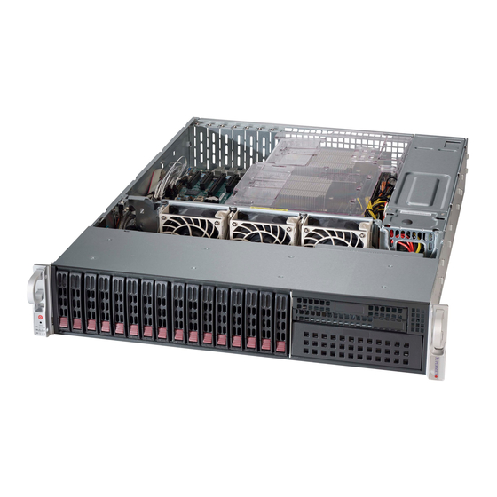
Chapter 1 Introduction Overview The Supermicro SC213 chassis features a direct-attached SAS3 backplane supporting sixteen 2.5" SAS/SATA hard disk drives. It has dual highly efficient redundant power supplies, an optional DVD drive, two USB ports, three 80mm fans, and room for seven PCI Express expansion cards. -
Page 9: Shipping List
SC213 Chassis Manual Shipping List Visit the Supermicro web site for the latest shipping lists and part numbers for your particular chassis model at www.supermicro.com. Chassis Features The SC213 3U high-performance chassis includes the following features: Motherboard Support The chassis supports motherboard sizes of 13.68" x 13.0", E-ATX, ATX form factors. -
Page 10: Returning Merchandise For Service
For faster service, RMA authorizations may be requested online (http://www. supermicro.com/support/rma/). Whenever possible, repack the chassis in the original Supermicro carton, using the original packaging material. If these are no longer available, be sure to pack the chassis securely, using packaging material to surround the chassis so that it does not shift within the carton and become damaged during shipping. - Page 11 SC213 Chassis Manual Notes...
-
Page 12: Chapter 2 Rack Installation
Chapter 2 Rack Installation Chapter 2 Rack Installation This chapter provides instructions for preparing and mounting your chassis in a rack. Unpacking the System You should inspect the box the chassis was shipped in and note if it was damaged in any way. -
Page 13: Warnings And Precautions
SC213 Chassis Manual Warnings and Precautions Rack Precautions • Ensure that the leveling jacks on the bottom of the rack are fully extended to the floor with the full weight of the rack resting on them. • In single rack installations, stabilizers should be attached to the rack. •... -
Page 14: Rack Mounting Considerations
Chapter 2 Rack Installation Rack Mounting Considerations Ambient Operating Temperature If installed in a closed or multi-unit rack assembly, the ambient operating temperature of the rack environment may be greater than the ambient temperature of the room. Therefore, consideration should be given to installing the equipment in an environment compatible with the manufacturer’s maximum rated ambient temperature (TMRA). -
Page 15: Installing The System Into A Rack
SC213 Chassis Manual Installing the System into a Rack This section provides information on installing the server into a rack unit with the rack rails provided. There are a variety of rack units on the market, so the assembly procedure may differ slightly. Refer to the installation instructions that came with your rack. -
Page 16: Releasing The Inner Rail
Chapter 2 Rack Installation Releasing the Inner Rail Each inner rail has a locking latch. This latch prevents the server from coming completely out of the rack when when the chassis is pulled out for servicing. To mount the rail onto the chassis, first release the inner rail from the outer rails. Releasing Inner Rail from the Outer Rails 1. -
Page 17: Installing The Inner Rails On The Chassis
SC213 Chassis Manual Installing the Inner Rails on the Chassis Installing the Inner Rails 1. Identify the left and right inner rails. They are labeled. 2. Place the inner rail firmly against the side of the chassis, aligning the hooks on the side of the chassis with the holes in the inner rail. -
Page 18: Installing The Outer Rails Onto The Rack
Chapter 2 Rack Installation Installing the Outer Rails onto the Rack Installing the Outer Rails 1. Press upward on the locking tab at the rear end of the middle rail. 2. Push the middle rail back into the outer rail. 3. -
Page 19: Sliding The Chassis Onto The Rack Rails
SC213 Chassis Manual Sliding the Chassis onto the Rack Rails Warning: Mounting the system into the rack requires at least two people to support the chassis during installation. Please follow safety recommendations printed on the rails. Installing the Chassis into a Rack 1. -
Page 20: Chapter 3 System Interface
Chapter 3: System Interface Chapter 3 System Interface Overview The server includes a control panel on the front that houses power buttons and status monitoring lights. The externally accessible hard drives display status lights. The power supply displays status lights visible from the back of the chassis. Figure 3-1. -
Page 21: Control Panel Buttons
SC213 Chassis Manual Control Panel Buttons The chassis includes two push-buttons that control power to the system. Power The main power switch applies or removes primary power from the power supply to the server but maintains standby power. To perform most maintenance tasks, unplug the system to remove all power.. -
Page 22: Nic2
Chapter 3: System Interface NIC2 Indicates network activity on GLAN2 when flashing. NIC1 Indicates network activity on GLAN1 when flashing. Information LED Alerts operator to several states, as noted in the table below. Information LED Status Description An overheat condition has occured. Continuously on and red (This may be caused by cable congestion.) Blinking red (1Hz) -
Page 23: Overheating
Some backplanes allow the overheat temperature to be set at 45, 50, or 55 by changing a jumper setting. For more information, consult the backplane user manual at www.supermicro.com. (Click Support, then the Manuals link.) Responses If the server overheats: 1. -
Page 24: Power Supply Leds
Chapter 3: System Interface Power Supply LEDs On the rear of the power supply module, an LED displays the status. • Solid Green: When illuminated, indicates that the power supply is on. • Solid Amber: When illuminated, indicates the power supply is plugged in and turned off, or the system is off but in an abnormal state. - Page 25 SC213 Chassis Manual Notes...
-
Page 26: Chapter 4 Chassis Setup And Maintenance
Chapter 4: Chassis Setup and Maintenance Chapter 4 Chassis Setup and Maintenance Overview This chapter covers the steps required to install components and perform maintenance on the chassis. The only tool required is a Phillips screwdriver. Review the warnings and precautions listed in the manual before setting up or servicing this chassis. -
Page 27: Removing Power From The System
SC213 Chassis Manual Removing Power from the System Before performing some setup or maintenance tasks, use the following procedure to ensure that power has been removed from the system. 1. Use the operating system to power down the node, following the on-screen prompts. -
Page 28: Removing The Chassis Cover
Chapter 4: Chassis Setup and Maintenance Removing the Chassis Cover Figure 4-4. Removing the Chassis Cover Removing the Chassis Cover 1. Press both release tabs at the same time to release the cover from the locked position. 2. Once the top cover has been released, slide the cover backwards, toward the rear of the chassis. -
Page 29: Installing Hard Drives
SC213 Chassis Manual Installing Hard Drives The chassis supports sixteen hot-swap hard drives. Only SAS or enterprise SATA HDDs are recommended. The drives are mounted in drive carriers to simplify their installation and removal from the chassis. These carriers also help promote proper airflow for the drive bays. - Page 30 Chapter 4: Chassis Setup and Maintenance Figure 4-6. Chassis Drive Carrier Installing a Hard Drive into a Drive Carrier 1. Insert a drive into the carrier with the PCB side facing down and the connector end toward the rear of the carrier. 2.
-
Page 31: Installing The Rear 2.5" Hard Drive Cage
SC213 Chassis Manual Installing the Rear 2.5" Hard Drive Cage (SC213B) The SC213B model chassis supports an optional hard drive cage for two additional 2.5" hot-swappable hard drives. The hard drive cage installs in the rear of the chassis next to the power supply. Once the hard drive cage has been installed, the 2.5"... - Page 32 Chapter 4: Chassis Setup and Maintenance 4. Loosen the two screws outside and one screw inside the opening of the hard drive cage as illustrated. 5. Orient the 2.5" rear hard drive cage as shown, aligning the opening at the end of the cage with the opening at the back of the chassis.
-
Page 33: Installing The Rear Drives Into Carriers
SC213 Chassis Manual Installing the Rear Drives into Carriers (SC213B) Figure 4-10. Removing the Dummy Drive from the Drive Carrier Installing a Hard Drive into a 2.5" Rear Drive Carrier 1. Insert a hard drive into the carrier with the PCB side facing down and the connector end toward the rear of the carrier. -
Page 34: Installing Expansion Cards
For the W models such as SC213AC-R920WB, and the U models such as SC213A-R720UB the chassis slots are horizontal. The U models allow a Supermicro universal I/O (UIO) card in addition to expansion cards. - Page 35 SC213 Chassis Manual supports an additional three full-height expansion cards and three low profile expan- sion cards. If the serverboard does not support a UIO, then the W model chassis supports four full-height expansion cards and three low profile expansion cards. Installing a UIO Card 1.
- Page 36 Chapter 4: Chassis Setup and Maintenance Shield Clamp for Full-Height Card This U model chassis is Shield Clamp for Low Profile Card pictured without the riser card bracket. Figure 4-14. Remove an Expansion Card Slot Shield 3. Attach the riser card(s) to the riser card bracket using screws. Note that there are different cards for the right and left side of the bracket.
-
Page 37: Installing The Air Shroud
SC213 Chassis Manual Installing the Air Shroud Air shrouds concentrate airflow to maximize fan efficiency. It does not require screws for installation. UIO models require an additional air shroud that must be installed before the main shroud.. Figure 4-15. Installing the Main Air Shroud Installing the Main Air Shroud 1. - Page 38 Chapter 4: Chassis Setup and Maintenance Figure 4-16. Installing the UIO Model Air Shroud An additional air shroud is required for high-powered CPUs, to provide extra cooling. Install the additional air shroud if necessary. Installing the UIO Air Shroud 1. Remove the left side break-away piece of the main air shroud. 2.
-
Page 39: Power Supply
The chassis has a redundant power supply. Redundant power supplies are hot- swappable, and can be changed without powering down the system. New units can be ordered directly from Supermicro. Replace a failed power module with the same model. This power supply is auto-switching capable. This enables it to automatically sense and operate at a 100v to 240v input voltage. -
Page 40: Installing The Power Distributor
Chapter 4: Chassis Setup and Maintenance Installing the Power Distributor The power distributor provides failover and power supply redundancy and is pre-installed in the chassis. In the rare event that you have to replace the power distributor, follow the steps below. Figure 4-18. -
Page 41: Removing The Backplane
SC213 Chassis Manual Removing the Backplane The backplane is located behind the hard drives and in front of the front system fans. In order to change jumper settings on the backplane, it may be necessary to remove the backplane from the chassis. Removing the Backplane from the Chassis 1. - Page 42 Chapter 4: Chassis Setup and Maintenance 5. Loosen but do not remove the three screws in the spring bar, located on the floor of the chassis, indicated by the arrows below. Figure 4-20. Loosening the Spring Bar Screws in the Floor of the Chassis 6.
-
Page 43: Appendix A Sc213 Power Supply Specifications
Appendix A: Power Supply Specifications Appendix A SC213 Power Supply Specifications This appendix lists power supply specifications for your chassis system. 920W (Redundant) MFR Part # PWS-920P-1R AC Input 100-240 V, 50-60 Hz, 11-4.5 Amp 4 Amp @ +5V standby DC Output 75 Amp @ +12V 740W (Redundant) - Page 44 SC213 Chassis Manual 900W (Redundant) MFR Part # PWS-902-1R AC Input 100 - 240V, 60-50Hz, 11-4.5 Amp +5V standby 4 Amp DC Output +12V 75 Amp +5V: 45 Amp DC Output +3.3V: 24 Amp with PDB -12V: 0.6 AmpVsb/4A 1200W (Redundant) MFR Part # PWS-1K23A-1R 100 - 127V, 60-50Hz, 15-12 Amps AC Input...
- Page 45 Supermicro's Technical Support department for assistance. Only certified technicians should attempt to install or configure components. Read this appendix in its entirety before installing or configuring components in the Supermicro chassis. These warnings may also be found on our website at http://www.supermicro.com/about/...
- Page 46 Appendix B: Standardized Warning Statements Warnung WICHTIGE SICHERHEITSHINWEISE Dieses Warnsymbol bedeutet Gefahr. Sie befinden sich in einer Situation, die zu Verletzungen führen kann. Machen Sie sich vor der Arbeit mit Geräten mit den Gefahren elektrischer Schaltungen und den üblichen Verfahren zur Vorbeugung vor Unfällen vertraut. Suchen Sie mit der am Ende jeder Warnung angegebenen Anweisungsnummer nach der jeweiligen Übersetzung in den übersetzten Sicherheitshinweisen, die zusammen mit diesem Gerät ausgeliefert wurden.
- Page 47 SC213 Chassis User's Manual !تحذٌز جسذٌة اصابة ًتتسبب ف حالة ٌوكي أى ًاًك ف خطز ًٌٌع هذا الزهز الذوائز بالوخاطز الٌاجوة عي ي على علن ، ك هعذات تعول على أي قبل أى الكهزبائٍة حىادث أي وقىع وٌع ل الىقائٍة سات...
- Page 48 Appendix B: Standardized Warning Statements Warnung Vor dem Anschließen des Systems an die Stromquelle die Installationsanweisungen lesen. ¡Advertencia! Lea las instrucciones de instalación antes de conectar el sistema a la red de alimentación. Attention Avant de brancher le système sur la source d'alimentation, consulter les directives d'installation. מתח...
- Page 49 SC213 Chassis User's Manual Warnung Dieses Produkt ist darauf angewiesen, dass im Gebäude ein Kurzschluss- bzw. Überstromschutz installiert ist. Stellen Sie sicher, dass der Nennwert der Schutzvorrichtung nicht mehr als: 250 V, 20 A beträgt. ¡Advertencia! Este equipo utiliza el sistema de protección contra cortocircuitos (o sobrecorrientes) del edificio.
- Page 50 Appendix B: Standardized Warning Statements Power Disconnection Warning Warning! The system must be disconnected from all sources of power and the power cord removed from the power supply module(s) before accessing the chassis interior to install or remove system components. 電源切断の警告...
- Page 51 SC213 Chassis User's Manual امداد وحدة من سهك انكهرباء وإزانت انطاقت مصادر من جميع اننظاو يجب فصم قبم انطاقت الجهاز مكىناث نتثبيج أو إزانت ههيكم ن انمناطق انداخهيت انىصىل إنى 경고! 시스템에 부품들을 장착하거나 제거하기 위해서는 섀시 내부에 접근하기 전에 반드시 전원 공급장치로부터...
- Page 52 Appendix B: Standardized Warning Statements Attention Il est vivement recommandé de confier l'installation, le remplacement et la maintenance de ces équipements à des personnels qualifiés et expérimentés. !אזהרה .הציוד או לתת שירות עבור הציוד אי להתקין, להחליף את צוות מוסמך בלבד רש هذا...
- Page 53 SC213 Chassis User's Manual Warnung Diese Einheit ist zur Installation in Bereichen mit beschränktem Zutritt vorgesehen. Der Zutritt zu derartigen Bereichen ist nur mit einem Spezialwerkzeug, Schloss und Schlüssel oder einer sonstigen Sicherheitsvorkehrung möglich. ¡Advertencia! Esta unidad ha sido diseñada para instalación en áreas de acceso restringido. Sólo puede obtenerse acceso a una de estas áreas mediante la utilización de una herramienta especial, cerradura con llave u otro medio de seguridad.
- Page 54 Appendix B: Standardized Warning Statements Battery Handling Warning! There is the danger of explosion if the battery is replaced incorrectly. Replace the battery only with the same or equivalent type recommended by the manufacturer. Dispose of used batteries according to the manufacturer's instructions 電池の取り扱い...
- Page 55 SC213 Chassis User's Manual فعليل بطريقة غير صحيحة البطارية انفجار في حالة اسحبذال من هناك خطر اسحبذال البطارية به الشرمة المصنعة أوصث مما أو ما يعادلها بنفس النىع فقط حعليمات الشرمة الصانعة المسحعملة وفقا ل جخلص من البطاريات 경고! 배터리가 올바르게 교체되지 않으면 폭발의 위험이 있습니다. 기존 배터리와 동일하거나 제 조사에서...
- Page 56 Appendix B: Standardized Warning Statements ¡Advertencia! Puede que esta unidad tenga más de una conexión para fuentes de alimentación. Para cortar por completo el suministro de energía, deben desconectarse todas las conexiones. Attention Cette unité peut avoir plus d'une connexion d'alimentation. Pour supprimer toute tension et tout courant électrique de l'unité, toutes les connexions d'alimentation doivent être débranchées.
- Page 57 SC213 Chassis User's Manual Backplane Voltage Warning! Hazardous voltage or energy is present on the backplane when the system is operating. Use caution when servicing. バックプレーンの電圧 システムの稼働中は危険な電圧または電力が、 バックプレーン上にかかっています。 修理する際には注意く ださい。 警告 当系险正在险行时,背板上有很危险的险压或能量,险行险修时险必小心。 警告 當系統正在進行時,背板上有危險的電壓或能量,進行維修時務必小心。 Warnung Wenn das System in Betrieb ist, treten auf der Rückwandplatine gefährliche Spannungen oder Energien auf.
- Page 58 Appendix B: Standardized Warning Statements اللىحة أوالطاقة المىجىدة على التيار الكهزبائي مه خطز هناك هذا الجهاس خدمة كه حذرا عند يعمل النظام عندما يكىن 경고! 시스템이 동작 중일 때 후면판 (Backplane)에는 위험한 전압이나 에너지가 발생 합니다. 서비스 작업 시 주의하십시오. Waarschuwing Een gevaarlijke spanning of energie is aanwezig op de backplane wanneer het systeem in gebruik is.
- Page 59 SC213 Chassis User's Manual ת ת י י א א ו ו ם ם ח ח ו ו ק ק י י ה ה ח ח ש ש מ מ ל ל ה ה א א ר ר צ צ י י !אזהרה...
- Page 60 Appendix B: Standardized Warning Statements Attention La mise au rebut ou le recyclage de ce produit sont généralement soumis à des lois et/ou directives de respect de l'environnement. Renseignez-vous auprès de l'organisme compétent. ס ס י י ל ל ו ו ק ק ה ה מ מ ו ו צ צ ר ר !אזהרה...
- Page 61 SC213 Chassis User's Manual Warnung Gefährlich Bewegende Teile. Von den bewegenden Lüfterblätter fern halten. Die Lüfter drehen sich u. U. noch, wenn die Lüfterbaugruppe aus dem Chassis genommen wird. Halten Sie Finger, Schraubendreher und andere Gegenstände von den Öffnungen des Lüftergehäuses entfernt.
- Page 62 Electrical Appliance and Material Safety Law prohibits the use of UL or CSA -certified cables (that have UL/CSA shown on the code) for any other electrical devices than products designated by Supermicro only. 電源コードとACアダプター...
- Page 63 .قيرح وأ لطع يف ببستي دق ىرخأ تالوحمو تالباك يأ مادختسا .ميلسلا سباقلاو لصوملا مجح لبق نم ةدمتعملا تالباكلا مادختسا تادعملاو ةيئابرهكلا ةزهجألل ةمالسلا نوناق رظحيUL وأCSA ( ةمالع لمحت يتلاوUL/CSA) لبق نم ةددحملاو ةينعملا تاجتنملا ريغ ىرخأ تادعم يأ عمSupermicro. B-19...
- Page 64 사항을 준수하여 제공되거나 지정된 연결 혹은 구매 케이블, 전원 케이블 및 AC 어댑터를 사용하십시오. 다른 케이블이나 어댑터를 사용하면 오작동이나 화재가 발생할 수 있습니다. 전기 용품 안전법은 UL 또는 CSA 인증 케이블 (코드에 UL / CSA가 표시된 케이블)을 Supermicro 가 지정한 제품 이외의 전기 장치에 사용하는 것을 금지합니다. Stroomkabel en AC-Adapter...
-
Page 65: Appendix C Bpn-Sas-213A Backplane Specifications
Appendix C: SAS-213A Backplane Specifications Appendix C BPN-SAS-213A Backplane Specifications To avoid personal injury and property damage, carefully follow all the safety steps listed below when accessing your system or handling the components. C-1 ESD Safety Guidelines Electrostatic Discharge (ESD) can damage electronic com ponents. To prevent dam- age to your system, it is important to handle it very carefully. -
Page 66: Version Information
This manual reflects BPN-SAS-213A Revision 1.00, the most current release avail- able at the time of publication. Always refer to the Supermicro Web site at www.su- permicro.com for the latest updates, compatible parts and supported configurations. -
Page 67: Rear Connectors And Jumpers
Appendix C: SAS-213A Backplane Specifications C-4 Rear Connectors and Jumpers The following connectors are on the side of the backplane that faces the rear of the chassis. They are marked by silkscreen labels. JP35 SAS IN#4 SAS IN#3 SAS IN#2 JSM4 JSM3 JSM2... -
Page 68: Rear Connector And Pin Definitions
SC213 Chassis Manual C-5 Rear Connector and Pin Definitions 1. Upgrade Connectors The upgrade connectors are designated JP69, and JP78 are used for manufacturer's diagnos- tic purposes only. 2. - 5. I C Connectors C Connector Pin Definitions The I C Connectors, designated JP37, JP95, Pin# Definition JP52 and JP96 are used to monitor HDD ac-... - Page 69 Appendix C: SAS-213A Backplane Specifications 11. - 12. ACT_IN: SAS Activity LED Header Pin Definitions The activity LED connectors, designated JP26, Pin# Definition Pin# Definition and JP27 are used to indicate the activity ACT IN#0 ACT IN#4 status of each SAS drive. The activity LED ACT IN#1 ACT IN#5 connector is located on the front panel.
-
Page 70: Rear Jumper Locations And Pin Definitions
SC213 Chassis Manual C-6 Rear Jumper Locations and Pin Definitions JP35 SAS IN#4 SAS IN#3 SAS IN#2 JSM4 JSM3 JSM2 9072#1 RST 1-2:RST JP69: UPGRADE#1 BAR CODE 2-3:NO RST C133 SAS IN#1 JP96 JP52 JP95 R125 JP37 R392 I2C#4 I2C#3 I2C#2 R624 I2C#1... -
Page 71: I 2 C And Sgpio Modes And Jumper Settings
Appendix C: SAS-213A Backplane Specifications C and SGPIO Modes and Jumper Settings This backplane can utilize I C or SGPIO. SGPIO is the default mode and can be used without making changes to your jumper. The following information details which jumper must be configured to use SGPIO mode or restore your backplane to I C mode. -
Page 72: Rear Led Indicators
SC213 Chassis Manual JP35 9072#1 RST 1-2:RST JP69: UPGRADE#1 Rear LED Indicators 2-3:NO RST C133 SAS IN#1 R125 JP37 R624 JSM1 I2C#1 R123 C132 R124 JP69 R131 JP35 JP84 C139 JP18 C380 JP84 MODE 1-2:SGPIO 2-3:I2C JP35 SAS IN#4 SAS IN#3 SAS IN#2 JSM4 JSM3... -
Page 73: Front Components, Connectors And Led Indicators
Appendix C: SAS-213A Backplane Specifications C-7 Front Components, Connectors and LED Indicators R614 R250 R173 R251 R180 R428 R467 R468 R461 R175 R164 R213 R179 R435 R165 R178 R214 R465 D104 R174 R215 R253 R466 R463 D110 D111 D107 R460 D108 D109 D106... - Page 74 SC213 Chassis Manual Front LED Indicators Hard Drive Activity Failure LED SAS #0 SAS #1 SAS #2 SAS #3 D102 D107 SAS #4 SAS #5 SAS #6 SAS #7 D104 D108 SAS #8 SAS #9 SAS #10 SAS #11 D106 D109 SAS #12 SAS #13...
-
Page 75: Appendix D Bpn-Sas3-213A Backplane Specifications
Appendix D: BPN-SAS3-213A Backplane Specifications Appendix D BPN-SAS3-213A Backplane Specifications This manual covers BPN-SAS3-213A connectors, jumpers and indicators. D-1 ESD Safety Guidelines Electrostatic Discharge (ESD) can damage electronic com ponents. To prevent damage to your system, it is important to handle it very carefully. The following measures are generally sufficient to protect your equipment from ESD. -
Page 76: Version Information
This manual reflects BPN-SAS3-213A Revision 1.00, the most current release available at the time of publication. Always refer to the Supermicro Web site at www.supermicro.com for the latest updates, compatible parts and supported... -
Page 77: Rear Connectors
Appendix D: BPN-SAS3-213A Backplane Specifications D-4 Rear Connectors The following connectors are on the side of the backplane that faces the rear of the chassis. They are marked by silkscreen labels. ATMEL#2 RESET UPGRADE #2 ATMEL#1 RESET UPGRADE #1 1-2:RESET 1-2:RESET 2-3:NO RESET 2-3:NO RESET... -
Page 78: Rear Connector And Pin Definitions
SC213 Chassis Manual D-5 Rear Connector and Pin Definitions 1. Backplane Main Power Connectors Backplane Main Power The 4-pin connectors, designated JP3, 4-Pin Connector JP4, JP5 and JP6 provide power to the Pin# Definition backplane. See the table on the right for +12V pin definitions. -
Page 79: Rear Jumper Locations And Pin Definitions
Appendix D: BPN-SAS3-213A Backplane Specifications D-6 Rear Jumper Locations and Pin Definitions ATMEL#2 RESET UPGRADE #2 UPGRADE #1 ATMEL#1 RESET 1-2:RESET 1-2:RESET 2-3:NO RESET 2-3:NO RESET BAR CODE C109 C110 C142 C111 C141 Figure D-2. Rear Jumpers Jumper Settings Jumper Description Chip reset, for manufacturing use only. -
Page 80: Front Connectors And Led Indicators
SC213 Chassis Manual D-7 Front Connectors and LED Indicators FAIL#15 ACT#15 LED13 LED15 LED21 LED23 FAIL#12 FAIL#13 LED29 ACT#5 FAIL#1 ACT#1 FAIL#5 FAIL#9 ACT#9 FAIL#0 ACT#0 FAIL#2 ACT#2 FAIL#3 ACT#3 FAIL#4 ACT#4 LED31 FAIL#6 ACT#6 FAIL#7 ACT#7 FAIL#8 ACT#8 FAIL#10 ACT#10 FAIL#11 ACT#11... - Page 81 Appendix D: BPN-SAS3-213A Backplane Specifications Notes...
- Page 82 SC213 Chassis Manual Disclaimer (cont.) The products sold by Supermicro are not intended for and will not be used in life sup- port systems, medical equipment, nuclear facilities or systems, aircraft, aircraft devices, aircraft/emergency communication devices or other critical systems whose failure to per- form be reasonably expected to result in significant injury or loss of life or catastrophic property damage.
-
Page 83: Appendix E Bpn-Sas3-213A-N8 Backplane Specifications
Appendix E BPN-SAS3-213A-N8 Backplane Specifications Appendix E BPN-SAS3-213A-N8 Backplane Specifications ESD Safety Guidelines Electrostatic Discharge (ESD) can damage electronic com ponents. To prevent dam- age to your system, it is important to handle it very carefully. The following measures are generally sufficient to protect your equipment from ESD. •... -
Page 84: Introduction To The Bpn-Sas3-213A-N8 Backplane
Introduction to the BPN-SAS3-213A-N8 Backplane The BPN-SAS3-213A-N8 backplane has been designed to utilize the most up- to-date technology available, providing your system with reliable, high-quality performance. Always refer to the Supermicro web site at www.supermicro.com for the latest updates, compatible parts, and supported configurations. -
Page 85: Front Connectors
Appendix E BPN-SAS3-213A-N8 Backplane Specifications Front Connectors Figure 2-1. Front Connectors Front Connectors 1. Power Connectors (4-pin): JPW3, 7. NVMe IN #15: CN8 JPW2, JPW1, JPW6, JPW5, and 8. NVMe IN #13: CN4 JPW4. 9. NVMe IN #11: CN7 2. Upgrade Connector: JP1 10. -
Page 86: Front Connector And Pin Definitions
BPN-SAS3-213A-N8 Backplane Manual Front Connector and Pin Definitions 1. Backplane Main Power Connectors Backplane Main Power The 4-pin connectors, designated JPW3, 4-Pin Connector JPW2, JPW1, JPW6, JPW5, and JPW4, pro- Pin# Definition vide power to the backplane. See the table on +12V the right for pin definitions. -
Page 87: Front Jumpers
Appendix E BPN-SAS3-213A-N8 Backplane Specifications Front Jumpers Figure 2-2. Front Jumpers Explanation of Jumpers Connector To modify the operation of the backplane, Pins jumpers can be used to choose between optional settings. Jumpers create shorts between two pins to change the function Jumper of the connector. - Page 88 BPN-SAS3-213A-N8 Backplane Manual Jumper Settings Jumper Description CPU_SEL0 CPU_SEL1 CPU_SEL2 I2C_SEL0 I2C_SEL1 NVMe drive connection 8+0 NVMe drive connection 4+4 (default for two 4-NVMe AOC interface) NVMe drive connection 2+6 NVMe drive connection 6+2 Reserved for future use. Open by default. BMC I2C address is 66h (default)
-
Page 89: Rear Components, Connectors, And Led Indicators
Appendix E BPN-SAS3-213A-N8 Backplane Specifications Rear Components, Connectors, and LED Indicators Figure 2-3. Rear SAS/SATA Connectors and LED Indicators SAS/SATA/NVMe Connectors and LED Indicators Rear SAS Drive Failure Activity Connector Number SAS3/SATA HDD #0 LED1 LED2 SAS3/SATA HDD #1 LED5 LED6 SAS3/SATA HDD #2 LED8... - Page 90 BPN-SAS3-213A-N8 Backplane Manual Disclaimer (cont.) The products sold by Supermicro are not intended for and will not be used in life support systems, medical equipment, nuclear facilities or systems, aircraft, aircraft devices, aircraft/emergency com- munication devices, or other critical systems whose failure to perform be reasonably expected to result in significant injury or loss of life or catastrophic property damage.
Need help?
Do you have a question about the SC213 Series and is the answer not in the manual?
Questions and answers