Sign In
Upload
Download
Table of Contents
Contents
Add to my manuals
Delete from my manuals
Share
URL of this page:
HTML Link:
Bookmark this page
Add
Manual will be automatically added to "My Manuals"
Print this page
×
Bookmark added
×
Added to my manuals
Manuals
Brands
Supermicro Manuals
Chassis
SC213LTQ
User manual
Supermicro SC213LTQ User Manual
Sc213l chassis series
Hide thumbs
1
2
3
4
5
Table Of Contents
6
7
8
9
10
11
12
13
14
15
16
17
18
19
20
21
22
23
24
25
26
27
28
29
30
31
32
33
34
35
36
37
38
39
40
41
42
43
44
45
46
47
48
49
50
51
52
53
54
55
56
57
58
59
60
61
62
63
64
65
66
page
of
66
Go
/
66
Contents
Table of Contents
Bookmarks
Table of Contents
Manual Organization
Table of Contents
Chapter 1 Introduction
Overview
Shipping List
Contacting Supermicro
Returning Merchandise for Service
Chapter 2 System Safety
Overview
Warnings and Precautions
Preparing for Setup
Electrical Safety Precautions
General Safety Precautions
System Safety
Chapter 3 System Interface
Overview
Control Panel Buttons
Control Panel Leds
Drive Carrier Leds
Chapter 4 Chassis Setup and Maintenance
Overview
Installation and General Maintenance
Installation Topics
General Maintenance Topics
Removing the Chassis Cover
Installing Hard Drives
Installing the I/O Shield
I/O Shield
Installing Chassis Standoffs
Permanent and Optional Standoffs
Installing the Motherboard
Installing the Add-On Cards
Installing Riser Cards and Add-On Cards in UIO Models
Installing the Air Shroud
Installing the Air Shroud in the Chassis
4-10 Checking the Air Flow
Installation Complete
4-11 System Fans
4-12 Power Supply
4-13 Installing the Power Distributor
4-14 Removing the Backplane
4-15 Installing the Backplane
Chapter 5 Rack Installation
Overview
Unpacking the System
Preparing for Setup
Choosing a Setup Location
Warnings and Precautions
Rack Precautions
General Server Precautions
Rack Mounting Considerations
Ambient Operating Temperature
Reduced Airflow
Mechanical Loading
Circuit Overloading
Reliable Ground
Rack Mounting Instructions
Identifying the Sections of the Rack Rails
Locking Tabs
Releasing the Inner Rail
Installing the Inner Rails on the Chassis
Installing the Outer Rails on the Rack
Standard Chassis Installation
Optional Quick Installation Method
Appendix A SC213L Chassis Cables
Appendix B SC213L Power Supply Specifications
Appendix C SAS-213LTQ Backplane Specifications
Explanation of Jumpers
Advertisement
Quick Links
Download this manual
S
UPER
®
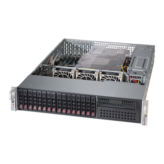
SC213L Chassis Series
SC213LTQ-R720LPB
SC213LTQ-R720UB
USER'S MANUAL
1.0a
Table of
Contents
Previous
Page
Next
Page
1
2
3
4
5
Advertisement
Table of Contents
Need help?
Do you have a question about the SC213LTQ and is the answer not in the manual?
Ask a question
Questions and answers
Related Manuals for Supermicro SC213LTQ
Chassis Supermicro SC216BAC-R920LPB User Manual
Sc216 chassis series (169 pages)
Chassis Supermicro SC216 Series User Manual
(169 pages)
Chassis Supermicro SC213AC-R1K23LPB User Manual
Sc213 chassis series (78 pages)
Chassis Supermicro SC213 Series User Manual
(90 pages)
Chassis Supermicro SC213XAC-R1K05LP User Manual
(62 pages)
Chassis Supermicro SUPERO SC217 Series User Manual
(96 pages)
Chassis Supermicro SC818 User Manual
Chassis series (32 pages)
Chassis Supermicro SCF418 Series User Manual
Supero scf418 series (87 pages)
Chassis Supermicro Supero SC933T-R760B User Manual
Sc933 chassis series (84 pages)
Chassis Supermicro SC846BE1C-R1K28B User Manual
(160 pages)
Chassis Supermicro SC113M Series User Manual
(62 pages)
Chassis Supermicro SC116 Series User Manual
(96 pages)
Chassis Supermicro SC101F User Manual
(37 pages)
Chassis Supermicro SC721 Series User Manual
(42 pages)
Chassis Supermicro SUPERO SC813M Series User Manual
(84 pages)
Chassis Supermicro SUPERO SC813MTQ-350CB User Manual
(84 pages)
This manual is also suitable for:
R720lpb
R720ub
Sc213ltq-r720lpb
Sc213ltq-r720ub
Table of Contents
Print
Rename the bookmark
Delete bookmark?
Delete from my manuals?
Login
Sign In
OR
Sign in with Facebook
Sign in with Google
Upload manual
Upload from disk
Upload from URL


Need help?
Do you have a question about the SC213LTQ and is the answer not in the manual?
Questions and answers