Table of Contents
Advertisement
Advertisement
Table of Contents

Subscribe to Our Youtube Channel
Related Manuals for Biotek Synergy HTX


Summary of Contents for Biotek Synergy HTX
- Page 1 Multi-Mode Microplate Reader Synergy ™ Operator’s Manual...
- Page 2 Canadian Department of Communications Class A .... xiv User Safety ..............xv Safety Symbols ............... xvi Introduction ................. 1 Synergy HTX Multi-Mode Microplate Reader ......2 Package Contents .............. 3 Optional Accessories ............4 Product Support & Service ..........5 Technical Assistance Center (TAC) ........
-
Page 3: Table Of Contents
Inspect/Clean Excitation and Emission Filters ....... 56 Flush/Purge the Fluid Path ..........57 Running a Dispense Protocol (Optional) ......58 Empty/Clean the Tip Priming Trough ........59 Clean the Priming Plate ............. 59 Clean the Internal Components .......... 60 BioTek Instruments, Inc. - Page 4 Absorbance Liquid Test 1 ..........110 Absorbance Liquid Test 2 ..........112 Absorbance Liquid Test 3 (optional) ......114 Fluorescence Tests ............116 Required Materials ............117 Test Solutions ............118 Procedure ..............119 Results Analysis ............119 Synergy HTX Operator’s Manual...
- Page 5 General Specifications ............. 144 Absorbance Specifications ..........145 Fluorescence Specifications ..........147 Luminescence Specifications ..........148 Models with Injectors ............149 Error Codes ..............151 Error Codes Overview ............152 Contact Info: BioTek Service/TAC ......... 152 Error Codes ..............153 BioTek Instruments, Inc.
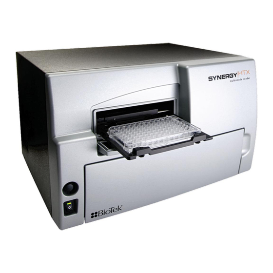
- Page 6 Chapter 1 Introduction This chapter introduces the Synergy HTX, describes its key features, lists its package contents, and provides contact information for technical assistance. Synergy HTX Multi-Mode Microplate Reader ....... 2 Package Contents ..............3 Optional Accessories ............... 4 Product Support & Service ............5 Technical Assistance Center (TAC) ........
- Page 7 Both Synergy HTX models support the reading of 6-, 12-, 24-, 48-, 96-, and 384-well microplates with standard 128 x 86 mm geometry, as well as the BioTek Take3 and Take3 Trio Micro-Volume Plates.
- Page 8 Package Contents | Package Contents Part numbers and package contents are subject to change. Contact BioTek Customer Care with any questions. Item Part # Synergy HTX Operator’s Manual 1341000 Power supply 76061 Power cord set (specific to installation environment):...
- Page 9 BioCell Quartz Vessel and Adapter Plate Additional Fluorescence Filters; contact BioTek for part numbers and availability The Synergy HTX is compatible with the BioStack Microplate Stacker. Contact BioTek or visit our website to learn more. For Use with Liquid Tests (see Chapter 5)
- Page 10 If your instrument(s) or software fails to function properly, if you have questions about how to use or maintain our products, or if you need to send an instrument to BioTek for service or repair, please contact our Technical Assistance Center. BioTek’s “TAC” is open from 8:30 AM to 5:30 PM (EST), Monday through Friday, excluding standard U.S.
-
Page 11: Getting Started
Chapter 3 Getting Started This chapter describes some of the Synergy HTX’s key components and provides an introduction to using Gen5 to control the instrument. Key Components ..............32 Power Switch, Carrier Eject Button, Microplate Carrier ... 32 Lamp Assembly and Filter Wheel Access ......33 Excitation and Emission Filter Wheels ......... -
Page 12: Key Components
X and Y axes to align each microwell with the top or bottom fluorescence probe, or bottom absorbance probe, as specified in the Gen5 procedure. When the read is complete, the plate carrier slides to its full-out position. BioTek Instruments, Inc. -
Page 13: Lamp Assembly And Filter Wheel Access
In Gen5, this option is found in a Read step within a Procedure. Refer to the Gen5 Help for further instructions. Lamp Assembly and Filter Wheel Access Applies only to Synergy HTX models with fluorescence and luminescence capability. Excitation filter wheel (TRF... -
Page 14: Excitation And Emission Filter Wheels
Chapter 3: Getting Started The Synergy HTX has two lamps: one for standard fluorescence, one for absorbance and time-resolved fluorescence: Standard Fluorescence: The 20-watt tungsten halogen lamp’s life is rated at an average of 1000 hours, and it is user-replaceable. The intensity of the bulb will slowly drop over time until the instrument’s... - Page 15 Figure 14: Profiles of the excitation and emission filter wheels, showing proper filter orientation The Synergy HTX is shipped with a set of excitation Important! and emission filters installed, and the Synergy HTX’s onboard software is preconfigured with the filter values and their locations.
- Page 16 Prepare a multi-layered “cushion” of lens paper. Using your finger covered with the lens paper, gently push against the filter and its C-clip retainer until they pop out. To replace a filter or plug: Hold the metal bracket with the filter wheel facing up. BioTek Instruments, Inc.
-
Page 17: Installing The Time-Resolved Fluorescence Cartridge
Turn on the instrument. Installing the Time-Resolved Fluorescence Cartridge For Synergy HTX models that support time-resolved fluorescence, the “TR” cartridge must be installed in place of the excitation filter wheel before a TRF assay can be run. The TR cartridge allows light from the xenon flash bulb to be input to the fluorescence optical system within the Synergy HTX. -
Page 18: Configuring The System For Luminescence Measurements
If you made any changes to either filter wheel, you must update Gen5’s filter table. Select “PLUG” to indicate the presence of a plug and “HOLE” to indicate an empty location. Click to download the information to the reader. Send Values Updating Gen5’s filter table; for complete instructions, see page 42. BioTek Instruments, Inc. -
Page 19: The External Dispense Module
Read steps and procedures. The External Dispense Module Applies only to Synergy HTX models with injectors. The dispense module pumps fluid from the supply bottles to injector heads located inside the instrument. Fluid is injected into one well at a time. - Page 20 PTFE tubes with threaded fittings on each end that are used to deliver fluid from the syringes to the instrument. Inside the Synergy HTX, two Teflon tubes transport fluid from the tubing ports on the rear of the instrument to the two injectors. As shown below, both injectors are positioned directly above the bottom fluorescence optical probe.
-
Page 21: Gen5 Software
Figure 18: Priming plate and tip priming trough Gen5 Software BioTek’s Gen5 software supports all Synergy HTX reader models. Use Gen5 to control the reader and the dispense module, perform data reduction and analysis on the measurement Synergy HTX Operator's Manual... -
Page 22: Viewing/Updating The Filter And Wavelengths Tables
Viewing/Updating the Filter and Wavelengths Tables If configured with fluorescence or luminescence capability, the Synergy HTX ships with a set of excitation and emission filters installed, and the reader’s onboard software is preconfigured with the filter values and their locations. When Gen5 establishes communication with the reader, it “asks”... -
Page 23: Creating Protocols And Experiments
After creating a protocol, create an experiment that references the protocol. You’ll run the experiment to read plates and analyze the data. Figure 19: Defining the procedure within a Gen5 protocol Synergy HTX Operator's Manual... - Page 24 . If prompted to select a reader, select the Protocol > Procedure and click Synergy HTX Select a plate type. The assay plate must match the plate type selected in Gen5. Otherwise, the results of the read may be invalid.
-
Page 25: Controlling The Dispense Module
If you have not already done so, save the file with an identifying name. Controlling the Dispense Module Applies only to Synergy HTX models with injectors. Gen5 is used to perform several dispense module-specific functions, including initializing, priming, and purging. Gen5 also contains certain configuration items that must be set before using the dispense module. - Page 26 Insert the appropriate inlet tube into the bottle. Place the priming plate on the carrier. Important! In Gen5, select System > Instrument Control > Synergy HTX click the tab. Prime Select the Dispenser number (1 or 2) associated with the supply bottle.
- Page 27 If a syringe needs to be installed or replaced, it must first be moved to its “Maintenance Position.” To do this using Gen5: Select and click the System > Instrument Control > Synergy HTX tab. Prime Select the appropriate Dispenser number (1 or 2) associated with the syringe.
-
Page 28: Recommendations For Optimum Performance
Gen5 protocol in advance as well, to ensure that the intended reading parameters are used and to avoid any last-minute corrections. Although the Synergy HTX supports standard flat, U-bottom, and V-bottom • microplates, the reader achieves optimum performance with optically clear, flat- bottomed wells. -
Page 29: Incubation And Partial Plates
Cluster your sample wells rather than spacing them throughout the plate. • Place your sample wells in the center of the plate. This placement may lead to less • evaporation than if you place the samples in wells on the edge of the plate. Synergy HTX Operator's Manual... -
Page 30: Preventive Maintenance
Chapter 4 Preventive Maintenance This chapter provides step-by-step instructions for maintaining the Synergy HTX and external dispense module (if used) in top condition, to ensure that they continue to perform to specification. Recommended Maintenance Schedule ........52 Overview ................ 52 Daily Cleaning for the Dispense Module ....... -
Page 31: Recommended Maintenance Schedule
(review the reagent’s package insert for specific recommendations). A daily cleaning regimen is the best way to ensure accurate performance and a long life for your instrument and dispense module. BioTek also recommends flushing the module with DI water before conducting the decontamination procedure described in Chapter 5, As-Needed Maintenance BioTek Instruments, Inc. -
Page 32: Recommended Maintenance Schedule
Models with injectors only: Flush/purge the fluid path (Optional) Run Dispense protocol Empty/clean tip prime trough Clean priming plate Clean internal components tubing and injector heads Clean optical probes Clean internal surfaces Synergy HTX Operator's Manual... -
Page 33: Warnings And Precautions
“wet” cloth on it. Do not allow water or other cleaning solution to run into the interior of the instrument. If this happens, contact BioTek’s Technical Assistance Center. Do not apply lubricants to the microplate carrier or Important! carrier track. -
Page 34: Cleaning Exposed Surfaces
“wet” cloth. Do not allow the cleaning solution to run into the interior of the instrument. If this happens, contact BioTek’s Service Department. Exposed surfaces may be cleaned (not decontaminated) with a cloth moistened (not soaked) with water or water and a mild detergent. You will need: Deionized or distilled water •... -
Page 35: Inspect/Clean Excitation And Emission Filters
Chapter 4: Preventive Maintenance Inspect/Clean Excitation and Emission Filters Applies only to Synergy HTX models with fluorescence and luminescence capability. Laboratory air is used to cool the lamp, and the filters can become dusty as a result. The filters should be inspected and cleaned at least every three months. You will need: Isopropyl, ethyl, or methyl alcohol •... -
Page 36: Flush/Purge The Fluid Path
Flush/Purge the Fluid Path | Flush/Purge the Fluid Path Applies only to Synergy HTX models with injectors. At the end of each day that the dispense module is in use, flush the fluid path using Gen5’s priming utility. Leave the fluid to soak overnight or over a weekend, and then purge the fluid before using the instrument again. -
Page 37: Running A Dispense Protocol (Optional)
Chapter 4: Preventive Maintenance Running a Dispense Protocol (Optional) Applies only to Synergy HTX models with injectors. After flushing/purging the system (page 57) and before running an assay that requires dispense, take a moment to visually inspect the dispensing accuracy. -
Page 38: Empty/Clean The Tip Priming Trough
Components Empty/Clean the Tip Priming Trough Applies only to Synergy HTX models with injectors. The tip priming trough is a small, removable priming cup located in the left rear of the microplate carrier, used for performing the Tip Prime. The trough holds about 1.5 mL of liquid and must be periodically emptied and cleaned by the user. -
Page 39: Clean The Internal Components
Chapter 4: Preventive Maintenance Clean the Internal Components Applies only to Synergy HTX models with injectors. The Synergy HTX’s internal components that require routine cleaning include: • Optical probes Surface beneath the microplate carrier • Internal dispense tubes and injector heads •... -
Page 40: Required Materials
Deionized or distilled water Stylus (stored in a plastic cylinder affixed to the rear of the dispense • module or reader) (PN 2872304) For cleaning the optical probes: • Clean cotton swabs Isopropyl alcohol • Lens-cleaning tissue • Synergy HTX Operator's Manual... -
Page 41: Removing The Reader's Shroud
Remove two screws from the top center of the rear panel Remove two side screws When reinstalling the shroud, press down firmly on the top to maintain a good seal while tightening the top screws. BioTek Instruments, Inc. - Page 42 Clean the Internal Components | Stand facing the front of the instrument. Grasp both sides of the shroud, slide it toward you, and pull it straight off the instrument. Set the shroud aside. Synergy HTX Operator's Manual...
-
Page 43: Removing The Internal Tubes And Injector Heads
When reinstalling the Important! internal dispense tubes, be sure to align the tubing ports with the injector heads as shown in this diagram. Look for the SYRINGE 1 SYRINGE 2 labels on the instrument’s rear panel. BioTek Instruments, Inc. - Page 44 Locate the tubing ports on the reader’s rear wall. Turn each tube’s thumbscrew counterclockwise and gently pull the tube from the port. Cable clamp Locate the injector heads. Turn each tube’s thumbscrew counterclockwise to disconnect the tube from the injector head. Synergy HTX Operator's Manual...
- Page 45 Chapter 4: Preventive Maintenance Turn the injector heads counterclockwise and gently pull them out of their sockets. Be sure to seat the injector tips securely when reinstalling. See the photo on page 77. BioTek Instruments, Inc.
-
Page 46: Cleaning The Internal Tubes And Injector Heads
Stream water from a faucet through the pipe to be sure it is clean. If the water does not stream out, try soaking the heads in hot soapy water and then reinserting the stylus. O-ring; do not remove Synergy HTX Operator's Manual... -
Page 47: Cleaning The Optical Probes
Instructions for removing and cleaning these components are provided on pages 64 through 67. Before starting this procedure, gather some supplies: • Small container of isopropyl alcohol Small container of deionized or distilled water Lens-cleaning tissue Cotton swabs BioTek Instruments, Inc. - Page 48 Screw for lowering Top optical probe and raising the top Incubator optical probe housing Top probe hanger, with two shoulder screws Figure 21: Internal components to be removed/adjusted for cleaning the optic probes Synergy HTX Operator's Manual...
- Page 49 Disconnect the heater and thermistor wires. To do this, depress the small tab (pictured below) and separate the connectors. Depress tab to separate the connectors Remove the thumbscrew located in the left rear of the instrument and set it aside. This exposes the ground wire. BioTek Instruments, Inc.
- Page 50 Clean the Internal Components | Lift the ground wire and move it off to the side. Locate the two black thumbscrews that hold the incubator housing in place. Remove both of them and set them aside. Synergy HTX Operator's Manual...
- Page 51 Gently lift the left side of the incubator housing and carefully slide it out. Note: When replacing the incubator housing, the two “forks” on its right side should wrap around the holding screws. The forks should not slide under the fixed foam housing. BioTek Instruments, Inc.
- Page 52 Use a 1/8" hex key to remove the top optical probe’s holding screw. Gently pull the optical probe up and out of its socket to expose it for cleaning. Soak the end of the probe in alcohol for one minute maximum Wipe with lens-cleaning tissue and set aside. Synergy HTX Operator's Manual...
- Page 53 (see instructions on the next page). Inspect the block Do not touch the lens with your fingers! for spills or other contamination. Carefully clean with mild detergent if necessary. BioTek Instruments, Inc.
- Page 54 Important! When cleaning the absorbance lens with the swab, apply very little pressure to the lens! Applying too much pressure can push the lens out of its holder; reinstallation must be performed by BioTek service personnel. If the lens does fall out, contact BioTek TAC.
-
Page 55: Cleaning The Reader's Internal Surface
(steps 1 through 6). Manually slide the microplate carrier to the left to engage the support pin, and then away from the center surface. Microplate carrier, fully extended BioTek Instruments, Inc. -
Page 56: Reassembling The Components
Insert the two injector heads into their sockets in the top probe hanger. Ensure that the Do not touch the absorbance lens with your fingers! injector heads are properly seated in the hanger. The knurled plastic should sit flush against the hanger surface, as shown below. Synergy HTX Operator's Manual... - Page 57 Do not overtighten the thumbscrews! Here is the top probe hanger ready for reinstallation, with injector heads and internal dispense tubes attached: Replace the top probe hanger and shoulder screws (using the 3/32" hex key), page 74. BioTek Instruments, Inc.
-
Page 58: Performance Check
After reassembling the instrument, perform the following to verify that the instrument is functioning properly: • Plug the instrument in and turn it on; allow its run-time system test to complete. Run a System Test through Gen5. Run any required OQ/PQ tests. • Synergy HTX Operator's Manual... - Page 59 Chapter 5 As-Needed Maintenance This appendix contains procedures for decontaminating all models of the Synergy HTX. Purpose ................82 Required Materials ..............83 Procedure for Models without Injectors ........84 Routine Procedure for Models with Injectors ......85 Clean Exposed Surfaces ............ 85 Decontaminate the Fluid Lines ...........
-
Page 60: As-Needed Maintenance
Centers for Disease Control and Prevention (CDC). Neither BioTek nor the CDC assumes any liability for the adequacy of these solutions and methods. Each laboratory must ensure that decontamination procedures are adequate for the Biohazard(s) they handle. -
Page 61: Required Materials
Required Materials | 83 Required Materials For all Synergy HTX models: Sodium hypochlorite (NaClO, or bleach) • • 70% isopropyl alcohol (as an alternative to bleach) • Deionized or distilled water Safety glasses • Surgical mask • Protective gloves •... -
Page 62: Procedure For Models Without Injectors
Do not immerse the instrument, spray it with liquid, or use a “wet” cloth. Do not allow the cleaning solution to run into the interior of the instrument. If this happens, contact the BioTek Service Department. ... -
Page 63: Routine Procedure For Models With Injectors
Routine Procedure for Models with Injectors Perform this Routine Procedure when all systems are functioning normally on the Synergy HTX with Injectors. If you are unable to prime the Synergy HTX due to a system failure, perform the Alternate Procedure described on page 89. -
Page 64: Decontaminate The Fluid Lines
Empty the beaker containing the outlet tubes. Put the tubes back in. Important! If sodium hypochlorite (bleach) was used, perform Rinse the Fluid on the next page. Lines Otherwise, (or after performing the Rinse procedure), repeat steps 1–13 for SYRINGE 2 / Dispenser 2. BioTek Instruments, Inc. -
Page 65: Rinse The Fluid Lines
Required Materials • Removing the Reader’s Shroud • Removing the Internal Tubes and Injector Heads • Cleaning the Internal Tubes and Injector Heads • When finished, replace the internal components and the reader’s shroud. Synergy HTX Operator’s Manual... -
Page 66: Clean The Tip Priming Trough And Priming Plate
If decontaminating with alcohol, remove the trough and plate and let them air- dry. Discard the used gloves and cloths using a biohazard trash bag and an approved biohazard container. tip priming trough Figure 33: Tip priming trough and priming plate BioTek Instruments, Inc. -
Page 67: Alternate Procedure For Models With Injectors
Alternate Procedure for Models with Injectors | 89 Alternate Procedure for Models with Injectors If you are unable to prime the Synergy HTX due to a system failure, decontaminate the instrument and the Dispense Module as follows: Turn to and perform the following... - Page 68 Use a clean, dry cloth to dry all wet surfaces on the instrument and the Dispense module. Reassemble the instrument and dispense module as necessary. Discard the used gloves and cloths using a biohazard trash bag and an approved biohazard container. BioTek Instruments, Inc.
- Page 69 Appendix B Error Codes This appendix lists and describes Synergy HTX error codes that may appear in Gen5. Error Codes Overview ............152 Contact Info: BioTek Service/TAC ........152 Error Codes ................ 153...
-
Page 70: Overview
Appendix B: Error Codes Error Codes Overview When a problem occurs during operation of the Synergy HTX, an error codes appears in Gen5. Error codes typically contain four characters, such as “2101,” and in most cases are accompanied by descriptive text. With many errors, the instrument will beep repeatedly;... - Page 71 If an error code appears in Gen5, look for it here. If you find the code, follow the suggestions provided for solving the problem. If you cannot find the code, of if you are unable to solve the problem, please contact BioTek’s Technical Assistance Center. The Gen5 Help system also provides troubleshooting tips.
- Page 72 Zones 1, 2, 3, and 4 • Turn the incubator on and wait at least 10 minutes for it to stabilize. Contact BioTek TAC. 2101 Plate dimensions incorrect. Row count < 1 or > 99. Review plate type defined in protocol. Ensure counts or dimensions do not exceed limits.
- Page 73 Volume calibration is needed to override defaults. 2C07 Verify that the dispenser calibration values have been loaded into Gen5. See the Installation chapter in the Synergy HTX Operator’s Manual. Contact BioTek TAC. 2D09 Tip prime volumes specified could overflow the tip priming trough.
- Page 74 Invalid rate selected for dispense. Select a valid rate. Call BioTek TAC. 2D28 Dispenser module not attached. Verify the cable is connected. Call BioTek TAC. 2D2A Dispense not primed successfully. Reinitialize the dispenser, then repeat the prime operation. Contact BioTek TAC.
- Page 75 Sensitivity too high. Chemistry too concentrated. Verify that the physical filter configuration matches the Gen5 Filter Table. 4810 PMT measurement offset test failure (offset is < 700 or > 2450 counts). Too much light in read chamber. Ensure the instrument enclosure is completely installed and secured. Synergy HTX Operator’s Manual...
- Page 76 Sensitivity set too high. Try adjusting sensitivity setting. Fluorescence standards dispensed to plate exceed value established by initial standard values recorded. Contamination within read chamber. Clean read chamber. Verify there is no filter wavelength overlaps between excitation and emission positions 2 and 3. BioTek Instruments, Inc.
- Page 77 Excitation filter wheel failed positional verify. 5403 Emission filter wheel failed positional verify. Ensure filter cartridge is fully inserted. 5700 Carrier x-axis obstructed. Carrier y-axis obstructed. 5701 Axis may have hit probe z-axis. Tip priming trough is not correctly inserted. Synergy HTX Operator’s Manual...
-
Page 78: System Test
The read was aborted and “home all axes” not performed. • • The carrier is inside the reader and the newly defined plate height is different from the most recently specified plate height. To resolve this error, eject the carrier before running the experiment. BioTek Instruments, Inc.
Need help?
Do you have a question about the Synergy HTX and is the answer not in the manual?
Questions and answers