Table of Contents
Advertisement
Quick Links
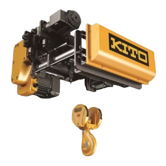
RY Series Wire Rope Hoist (10t)
Disassembly and Reassembly Manual
Safety Precaution
This Disassembly and Reassembly Manual includes contents to prevent injury to any person performing
Disassembly and reassembly, users, and other persons and damage to property, and to disassemble/
reassemble the Wire rope hoist safely and correctly.
Disassembling and reassembling the rope hoist is an essential part of periodic inspections and repairs. Refer
to the "RY Series Wire Rope Hoist (10t) Owner's Manual" (separate document) and carry out the procedures
correctly.
Persons performing disassembly/reassembly
Disassembly/reassembly shall be performed by a competent person (a person duly authorized by the company
as having expertise on the structure and device of the Wire rope hoist) or consult KITO.
Low Headroom Type:RYL
AS-RYL100-MGE-01
1
Advertisement
Table of Contents

Subscribe to Our Youtube Channel
Related Manuals for KITO RY Series


Summary of Contents for KITO RY Series
- Page 1 Wire rope hoist safely and correctly. Disassembling and reassembling the rope hoist is an essential part of periodic inspections and repairs. Refer to the "RY Series Wire Rope Hoist (10t) Owner's Manual" (separate document) and carry out the procedures correctly.
-
Page 2: Safety Precautions
Safety Precautions Improper use of the hoist may cause serious accidents resulting in death or severe injury such as drop of lifted load. Read this Disassembly and Reassembly Manual carefully before installation, operation and maintenance. Use the product after understanding the product knowledge, safety information and precautions. This Disassembly and Reassembly Manual classifies the safety information and precautions into three catego- ries of "DANGER", "WARNING", and "CAUTION". - Page 3 Disassembly/reassembly by anyone other than competent persons may result in death or sever injury. Prohibited • Do not use unauthorized parts for RY Series Wire Rope Hoist. Even if the part is an authorized part, it may not be used for a different model.
- Page 4 • When reassembling, replace the following parts with new ones. • Lubricating oil (The type and amount of oil required will vary depending on the specifications and size of the unit. Refer to "RY Series Wire Rope Hoist (10t) Owner's Manual" (separate document).) Mandatory •...
-
Page 5: Table Of Contents
Table of Contents Safety Precautions ............2 Table of Contents .............5 Disassembly and assembly tool ........6 Major parts in common ............7 Name of parts..............8 Disassembly procedure ...........9 1. Wire rope ..................9 2. Hook block .................13 3. Anchorage .................15 4. Idle sheave ................17 5. -
Page 6: Disassembly And Assembly Tool
Disassembly and assembly tool For disassembly and reassembly, prepare the following tools. Tool/jig name Application Icon Wrench 8mm/10mm/13mm/16mm//17mm/18mm/19mm/24m- Bolts and nuts m/30mm/36mm Hexagon wrench Socket bolts 3mm/5mm/6mm/8mm/10mm/14mm Snap ring pliers S Snap rings (shaft) Snap ring pliers R Snap rings (hole) Socket wrench 8mm/10mm/13mm/16mm/17mm/18mm/19mm/24mm/30m- Bolts and nuts... -
Page 7: Major Parts In Common
Major parts in common Difference 150-350 351-500 Rail width (mm) Lifting range (mm) Frame A, B, C, and D Length Suspension shaft Length Adjusting bolt Length Drive shaft Length Drum Length Support shaft Length Limit switch bolt Length Drum cover Length Counter weight Length... -
Page 8: Name Of Parts
Name of parts Idle sheave Gear box Rope drum Guide roller Motor (for lifting) Adjusting bolt Upper lower limit switch Suspension shaft Hook Hook latch Wire rope Anchorage Wheel Rope guide Direct limit switch Motor (for traversing) Control box Counter weight... -
Page 9: Disassembly Procedure
Disassembly procedure DANGER • Do not disassemble the rope hoist while it is being suspended. Doing so may result in death or severe injury due to a falling part. Place it on the floor and perform maintenance on the workbench. Prohibited The overall disassembly procedure is shown below. - Page 10 (5) Tap lightly the tip of the cotter, and pull out the cotter from the socket. If it is difficult to tap the tip of the cotter, put a • flathead screwdriver on the cotter as shown in the figure and tap the screwdriver with a hammer. Cotter Plastic hammer Flathead screwdriver...
- Page 11 Shim Guide C (10) Remove the bolt fixing Guide B, and remove Guide B Guide B from Guide C along the Support Guide A Guide B Shaft. Guide C Structure of Rope Loosen the socket bolt (11) Loosen the socket bolt indicated by the arrow in the figure below.
- Page 12 (16) Perform unwinding operation while pulling the Wire Rope by hand so that the Wire Rope does not float away from the Rope Drum. Remove in advance the Wire Rope to the position of the Rope Clamp as shown right. (Fixed state) (17) Loosen socket bolts and remove Wire...
-
Page 13: Hook Block
Hook block ■ Removing the hook block (1) Pull out the spring pin fixing the hook nut and hook. Pin punch Hook nut Spring pin (2) Remove the hook nut fixing the hook. Hook nut Hook (3) Remove the thrust bearing from the hook. Hook Thrust bearing (4) Remove the hook from the trunnion hole. - Page 14 (7) Remove the snap ring fixing the sheave subassembly. Snap ring (8) Remove the sheave subassembly from the trunnion subassembly shaft. Sheave subassembly Trunnion subassembly shaft (9) Remove the sheave cover B from the trunnion Sheave cover B subassembly. Trunnion subassembly (10) Remove the spring pin from the bracket.
-
Page 15: Anchorage
Anchorage ■ Removing the anchorage (1) Remove the socket bolts and spring lock washers (two locations for each) of the key plate fixing the shaft of the anchorage, and Spring lock remove the key plate. washer Shaft [5mm] Anchorage Socket bolt Key plate (2) Pull out the shaft of the anchorage from the hole of the beam A, and remove the... - Page 16 (4) Hammer the cotter tip gently, and pull out the cotter from the socket. If it is difficult to tap the tip of the cotter, put a • flathead screwdriver on the cotter as shown in the Cotter figure and tap the screwdriver with a hammer. Plastic hammer Flathead screwdriver (5) Remove the wire rope from the socket.
-
Page 17: Idle Sheave
Idle sheave ■ Removing the idle sheave (1) Remove the socket bolts (two locations) of Sheave support the key plate fixing the sheave support, and remove the key plate. [5mm] Socket bolt Spring lock washer Key plate (2) While supporting the idle sheave to prevent Sheave support it from falling, pull the sheave support out of the hole in beam B and remove the... -
Page 18: Rope Drum
Rope drum ■ Removing the lifting motor harness (terminal box side) (1) Cut the tie that binds the lifting motor Lifting motor harness Lifting motor harness harness. 200V 400V Cable band Cable band (2) Remove the round head screws (four locations each) securing the terminal cover, and then remove the terminal cover. - Page 19 ■ Removing the LS harness (1) Remove the socket bolts, spring lock washers, and large plain washers (eight locations for Drum cover each) installing the drum cover. [3mm/5mm] Large plain washer Spring lock washer Socket bolt (2) Cut all the cable bands fixing the LS harness Support shaft to the support shaft and mount base.
- Page 20 (5) Pull out the LS harness from the wiring cover, and return the wiring cover to the limit switch. LS harness Wiring cover (6) Cut the cable band bundling the DLS harness and LS harness on the control box Suspension side, and pull out the LS harness from the DLS harness shaft...
- Page 21 ■ Disassembling the rope drum (1) Place the rope drum assembly on sleepers Drum frame B with drum frame B facing up as shown in the figure. (2) Remove the three socket bolts and spring Hex nut lock washers and the one hex nut and spring Socket bolt lock washer from drum frame B.
- Page 22 (7) Wind the fiber sling around the rope drum. While lifting the rope drum with a crane gradually, pull it out straight. Rope drum (8) Remove drum frame A by tapping it with a Drum frame A plastic hammer from the back side of drum frame A.
-
Page 23: Lifting Motor
Lifting motor ■ Removing the lifting motor (1) Remove the nuts and spring lock washers (eight locations) securing the lifting motor, and remove the lifting motor from the gear box. Lifting motor [17mm] Spring lock washer ■ Disassembling the lifting motor (1) Place the removed lifting motor upright on the sleeper. - Page 24 (4) Remove the snap ring that is attached to the Snap ring motor shaft. Motor shaft Electromagnetic brake (5) Loosen the socket bolts securing the Socket bolt Plain washer electromagnetic brake (four locations), and Electromagnetic then remove the electromagnetic brake. brake [6mm] Brake hub...
- Page 25 (9) Burn the screw section as shown in the figure with a gas burner to melt the thread lock. Burn using a gas burner (10) Remove the socket bolts and spring lock washers (four locations each). [6mm] Socket bolt Spring lock washer Back flange Front flange Socket bolt...
- Page 26 (13) Wrap a fiber sling around the stator and pull it straight out while gradually lifting the stator with a crane. Fiber sling Stator Front flange ■ Disassembling the gear box (1) Suspend the gear box, remove the drain bolt on the bottom side, and drain the oil.
- Page 27 (6) Remove the bearing at the end of the gear Bearing 4 subassembly, and then remove the gear 4 Gear 4 subassembly. subassembly (7) Remove the bearing at the end of the gear 6 Bearing subassembly, and then remove gear 6, the Gear 6 gear shaft, and the bearing (gear case side).
-
Page 28: Direct Limit Switch
Direct limit switch ■ Removing the direct limit switch (1) Remove the hex nut fixing the fixing bracket of the direct limit switch, and remove the direct limit switch from the suspension shaft. Suspension [16mm (17mm)] shaft Fixing bracket Hex nut ■... - Page 29 (6) Loosen hex nut B, pull out the fixing bolt, and Hex nut B remove the sensor bracket. Sensor bracket [16mm (17mm)] Hex nut A Fixing bolt ■ Removing the DLS harness (1) Cut the cable band fixing the DLS harness to the adjusting bolt.
-
Page 30: Control Box
Control box ■ Removing the resistor harness (1) Remove the socket bolts, spring lock washers, and nuts (four locations each), and then Resister cover remove the resistor cover from the resistor Spring lock washer plate. Socket bolt [4mm] [8mm] Resistor plate CAUTION The resistor cover is hot after the rope hoist is operated. - Page 31 ■ Removing the resistor plate and resistor support bracket L/R (1) Remove the socket bolts and spring lock washers (four locations each), and then remove the resistor plate. [6mm] Resistor plate Socket bolt Spring lock washer (2) Remove the socket bolts and spring lock washers (two locations each), and then remove the resistor support bracket L/R.
- Page 32 (4) Remove the hex nuts (two locations) of the adjusting bolt outside of the counter weight. [36mm] Adjusting bolt Hex nut (5) Remove the socket bolts and spring lock washers (two locations each). [14mm] Socket bolt Spring lock washer (6) Remove the control box unit together with the counterweight while pulling the lifting motor harness out of the suspension shaft.
- Page 33 (3) Pull the harness out from the lifting inverter. Loosen the screw of the lead wire screwed to the lifting inverter and remove the lead wire. For details, see the wiring diagram provided in • the "RY Series Wire Rope Hoist (10t) Owner's Manual".
- Page 34 For details, see the wiring diagram provided in • the "RY Series Wire Rope Hoist (10t) Owner's Manual". (6) Remove the round head screws and spring lock washers (four locations for each) fixing the traversing inverter, and remove the traversing inverter.
- Page 35 For details, see the wiring diagram provided in • the "RY Series Wire Rope Hoist (10t) Owner's Manual". (2) Remove the round head screws (two locations for each: four locations in total) fixing the terminal blocks (two locations), and remove the terminal blocks.
-
Page 36: Traversing Motor
Traversing motor ■ Removing the traversing motor harness (terminal box side) (1) Cut the cable band fixing the traversing Cable band motor harness to the adjusting bolt. Adjusting bolt Traversing motor harness (2) Remove the round head screws and spring Round head screw lock washers (four locations for each), and Spring lock washer... - Page 37 ■ Removing the traversing motor (1) Wrap a fiber sling around the traversing Fiber sling motor to support the traversing motor. Traversing motor (2) Remove the socket bolts and spring lock Socket bolt Spring lock washer washers (four locations for each), and remove the traversing motor.
- Page 38 (4) Remove the socket bolts (three locations). [5mm] Socket bolt (5) Apply the flat screwdriver (-) to the insertion Electromagnetic brake assembly positions (two locations). Hammer it gently with the plastic hammer, and remove the electromagnetic brake assembly. Slit Brake lead wire Electromagnetic brake assembly (6) Make sure not to let the brake lead wire get caught in the cast hole in the terminal box.
- Page 39 (10) Remove the socket bolts (four locations) securing the brake bracket. Socket bolt Socket bolt [5mm] (11) Apply the screwdriver (-) to the insertion Screwdriver (-) insertion position position. Hammer the screwdriver gently with the plastic hammer, and remove the brake bracket.
- Page 40 (2) Remove the snap ring of the pinion. Pinion Snap ring Gear case A (3) Apply the round bar to the pinion. Hammer Pinion the round bar gently with the plastic hammer, and remove the pinion from the gear case A. Plastic hammer Round bar (4) Remove the gear 2 and collar A.
-
Page 41: Trolley Frame
10. Trolley frame ■ Removing the frame A/B/C/D (1) Remove the hex nuts (three locations) on the Frame D frame A exterior. [36mm] Frame C Frame B Remove the hex nuts on the exterior of frame C • in the same way. Frame A Adjusting bolt Hex nut... - Page 42 (6) Install the M12 eye type bolts in the screw holes (two locations) on the top of the beam, Chain sling Beam B and suspend with a crane through the chain Eye type bolt sling so that tension is applied to the chain sling.
- Page 43 ● Removing the wheel A (1) Remove the socket bolts, spring lock Socket bolt washers, and plain washers (three locations Spring lock washer each) securing the wheel cover, and then Plain washer remove the wheel cover. Wheel cover [5mm] (2) Remove the snap ring fixing the wheel A, and remove the wheel A from the axle.
- Page 44 (3) Lightly tap the tip of the guide roller jig with a plastic hammer to disassemble it as shown in Guide roller shaft the figure. Plastic hammer Collar Bearing Guide roller Guide roller shaft ● Removing the wheel B (1) Remove the snap ring fixing the wheel B, and remove the wheel B from the axle.
-
Page 45: Reassembly Procedures
Reassembly Procedures Trolley frame ■ Reassembling Frame A (Frame B) The reassembly procedure for frame B is the same as for frame A. • ● Installing wheel A (1) Install the bearing into frame A and secure it with the snap ring. Bearing Snap ring (2) Secure the idle gear with the snap ring for... - Page 46 (2) Secure the rubber buffer to the frame A with Rubber buffer a socket bolt. Socket bolt [6mm] Torque M8 torque setting: 18N•m (3) Secure the guide roller to the frame A by Rubber buffer using socket bolts and spring lock washers Guide roller (two locations).
- Page 47 (3) Secure the guide roller to the frame A by using socket bolts and spring lock washers Spring lock washers (two locations). Rubber buffer Socket bolts Guide roller [8mm] Spring lock washers Torque Socket bolts M10 torque setting: 35N•m Side view Guide roller ■...
- Page 48 (5) Secure the key plate to frame B by using the socket bolts and spring lock washers (two Frame B Frame A locations). Socket bolt [5mm] Key plate Torque Suspension shaft M6 torque setting: 8N•m (6) Insert the adjusting bolt into frame A and Frame A Frame B frame B, and then secure it using the outer...
-
Page 49: Traversing Motor
Traversing motor (1) Insert two bearings into Gear Case A, and then fix them in place with a snap ring. Gear Case A Snap ring Bearing (2) Hold a round bar against a pinion, and then with a plastic hammer, lightly tap on the Pinion round bar to insert the pinion. - Page 50 (6) With a plastic hammer, drive two pins into the gear case. Pins Pins (7) Install a packing, making sure that the pins are aligned with the holes on the packing. Packing Pins (8) Install Gear Case B by screwing in four Gear Case B socket bolts from the pinion side, making sure that the pins are aligned with the holes...
- Page 51 (11) Install a spring pin to the stator by lightly tap- ping on it with a plastic hammer. Spring pin (12) Install a brake bracket, making sure that the spring pin is aligned with the hole on the brake bracket. Align this hole with the spring pin.
- Page 52 Brake spring the spring holder, screw in an adjusting bolt. [10mm] Spring holder [35mm] (Monkey wrench recommended) For details about how to adjust the brake, see • Adjusting bolt the "RY Series Wire Rope Hoist (10t) Owner's Manual".
- Page 53 (21) After tightening the adjusting bolt to the designated brake torque, screw in a lock nut to prevent the adjusting bolt from becoming loose. [10mm] [35mm] Lock nut (Monkey wrench recommended) (22) Lay the lead wire routed to the terminal box Where each end of the lead as shown in the figure to the right.
- Page 54 (2) Wrap black plastic tape around the traversing motor harness about four times, and then Packing pass the traversing motor harness through the cable holder and the packing. Plastic tape For details, see the following illustration Traversing motor harness that shows where tape should be wrapped Cable holder around.
-
Page 55: Control Box
Control box (1) Lay the ground wire over the internal plate and route it to the control box. Hex nut [13mm] Internal plate Ground wire (2) Fix each of the two terminals in place by using two round head screws, two plain washers, and two spring lock washers. - Page 56 (6) Connect each harness to an inverter or a terminal. For details, see the wiring diagram provided in • the "RY Series Wire Rope Hoist (10t) Owner's Manual". (7) Tie harnesses together with a cable band. Do not tie the resister line and the power line •...
- Page 57 ■ Installing the control box (1) Fix the control box to the counter weight by Socket bolts using four socket bolts and four spring lock Spring lock washers washers. Counter weight [10mm] Torque Socket bolts Spring lock washers M12 torque setting: 60N•m (2) Close the lid on the control box by using Machine screw with eight machine screw with spring lock...
- Page 58 (4) While inserting the lifting motor harness into the suspension shaft, install the control box unit to both the suspension shaft and the adjusting bolt. Adjusting bolt Suspension shaft Lifting motor harness Control box unit (5) Put through the counter weight and install socket bolts and spring lock washers (two locations) to the suspension shaft.
- Page 59 ■ Installing lifting resistors (1) Secure the lifting resistors to the resistor plate using socket bolts and spring lock Resistor plate washers (two locations each). Spring lock washer [5mm] Socket bolt Lifting resistor [10mm] Torque M6 torque setting: 8N•m Round head screw (2) Connect a resister harness to each lifting Spring lock washer Mount base...
-
Page 60: Direct Limit Switch
Direct Limit Switch ■ Installing the DLS harness (1) Pass a DLS harness through the suspension shaft located on the right of the control box, and pull it out from the rope-drum side. DLS harness (2) Insert the DLS harness into the wiring cover DLS harness of the limit switch of the direct limit switch. - Page 61 (6) With a cable band, tie the inserted DLS harness and the two LS harnesses together Suspension at the entry point to the suspension shaft. shaft DLS harness Tie the harnesses together making sure that • they are aligned according to the positions of Cable band LS harness the cable glands that accept them.
- Page 62 (5) As shown in the figure to the right, insert the Hole on the sensor bracket Hole on the lever bracket claws of the spring into the holes on the sen- sor bracket and the lever bracket. Lever bracket Sensor bracket Claws of the spring Spring Before the insertion...
-
Page 63: Lifting Motor
Lifting motor ■ Assembling the gear box (1) Place the gear case on the sleepers with the gear case lid side facing up. Gear case Sleeper (2) Install the bearing. Use a press-fitting jig. • Pinion Apply lubricant to the outer circumference. •... - Page 64 Apply lubricant to the outer surface of the Bearing bearing for pinion, and insert it onto the Pinion pinion. Install the set pins (two locations) and apply the liquid gasket to the gear case lid mating surface. Set pin Set pin Liquid packing: 1222C made by ThreeBond •...
- Page 65 Oil seal for gear shaft (13) Use a press-fitting jig to press the oil seal Oil seal for for pinion into place. pinion shaft Use a press-fitting jig. • Outer side Gear case side Outer circumference (14) Install the drain bolt and tighten it to the gear case.
- Page 66 (2) Insert the rotor onto the stator. Rotor Stator (3) Install the back flange. Liquid packing: 1222C made by ThreeBond • When applying liquid packing to the mating • Back flange surface of parts, pay attention to the points Apply liquid packing below: (1) The mating surface must be degreased sufficiently.
- Page 67 (5) Install a snap ring. Snap ring (6) Install the brake hub and key. Brake hub (7) Install a snap ring. Snap ring Brake hub (8) Secure the electromagnetic brake using Socket bolt Plain washer socket bolts (four locations). Electromagnetic brake [8mm] Torque...
- Page 68 (10) Install the fan using a snap ring. Snap ring (11) Secure the fan cover using toothed lock bolts (four locations). Fan cover Toothed lock bolt Electromagnetic brake ■ Installing the lifting motor (1) Secure the lifting motor to the gear box with nuts and spring lock washers (8 locations).
-
Page 69: Rope Drum
Rope drum ■ Assembling the rope drum (1) Install drum frame A to the gear box by tap- Drum frame A ping it with a plastic hammer. Plastic hammer Gear box (2) Wrap a fiber sling around the rope drum and lift the rope drum to insert it onto the gear shaft. - Page 70 (5) Secure the gear box side cover bracket using socket bolts and spring lock washers (two locations for each). Cover bracket [5mm] Torque Socket bolt Spring lock washer M6 torque setting: 8N•m (6) Secure the drum frame B using three socket Hex nut bolts and spring lock washers and the one Socket bolt...
- Page 71 (3) Secure drum frame A and drum frame B Drum frame A Hex bolt Spring lock washer using the hex bolts and spring lock washers at each of the four locations. [24mm] Torque M16 torque setting: 120N•m Drum frame B Hex bolt Spring lock washer Open the oil plug (air breather) and put...
- Page 72 Other than Australia 135±3 114±3 For details on how to adjust the stop position, refer to "RY Series Wire Rope Hoist (10t) Owner's Manual". (7) As shown in the figure to the right, lay the Secured to the support shaft...
- Page 73 (9) Secure the drum cover using socket bolts, Drum cover spring lock washers, and large plain washers (8 locations for each). [3mm/5mm] Torque M4 torque setting: 2N•m Large plain washer M6 torque setting: 8N•m Spring lock washer Socket bolt ■ Installing the lifting motor harness Lifting motor harness Lifting motor harness (1) Tie together the lifting motor harness on...
-
Page 74: Idle Sheave
Idle Sheave ■ Assembling the idle sheave (1) Slide a collar, a sheave hanger, and then a Idle sheave shaft sheave onto the sheave shaft, in that order. Sheave hanger Collar (2) Align the key plate to the groove on the sheave shaft, and then secure using socket Collar bolts and spring lock washers... -
Page 75: Anchorage
Anchorage ■ Assembling the anchorage (1) Draw a wire rope through a sheave hanger. Pay attention to the position of the socket Socket (remember to draw a wire rope through the side that has no R attached to it). (2) Insert a cotter. Wire rope (3) Draw a wire rope through a gap between the cotter and the socket. - Page 76 ■ Installing the anchorage (1) Install the shaft of the anchorage to Beam Beam Subassembly A Subassembly A and the anchorage subas- sembly. Shaft Anchorage subassembly (2) Align a key plate to the groove on the shaft of the anchorage, and then fix it in place by using two socket bolts and two spring lock washers.
-
Page 77: Hook Block
Hook Block ■ Assembling the hook block Press the spring pin into the bracket. Bracket Spring pin (2) Install the sheave cover B onto the trunnion Sheave Cover B subassembly. Trunnion subassembly (3) Install the sheave assembly on the trunnion subassembly shaft. - Page 78 (7) Insert the hook into the trunnion hole. Trunnion hole Hook (8) Install the thrust bearing on the hook. Make sure that the bearing is correctly • positioned when you fit it onto the hook. Upper surface Side view of the thrust bearing Bottom surface Hook Thrust bearing...
-
Page 79: Installing The Wire Rope
10. Installing the Wire Rope WARNING • Wind the Wire Rope following the wire rope groove on the Rope Drum. Convex part Winding the Wire Rope over the convex part of the wire rope groove (refer to the figure on the right) will not only impair the proper functionality and performance of the Wire Rope Hoist, but could also cause the Wire Rope Hoist Mandatory to malfunction, resulting in a serious accident. - Page 80 (5) After fixing the Wire Rope, rotate the Rope Drum slowly, and place the Wire Rope in the Rope Drum’s groove from the groove’s start point. When doing so, lightly pull on the Wire Rope while rotating the Rope Drum in the lifting direction to prevent the Wire Rope from floating as you place the Wire Rope in the groove of the Rope Drum.
- Page 81 7-4. As shown in the figure on the right, rotate Guide A and Guide C along the Rope Drum using the Guide Roller as a guide. Rope drum Guide roller (8) Move Guide A toward the Reduction Gear Tighten the socket bolt side until its Guide Roller lies on the Wire Rope on the Rope Drum, and tighten the Drum Frame B side...
- Page 82 (12) Pass the Wire Rope through the other Wire rope Hook Sheave of the Hook Block. Hook Sheave (13) Draw a wire rope through a socket. Pay attention to the position of the sheave hanger Socket (remember to draw a wire rope through the side that has no R attached to it).
- Page 83 (17) From the inner side, insert an anchorage Hanger shaft into the part fixing the rope end in place on the main unit. Anchorage shaft Remove kinks from the wire rope, and then • with the sheave hanger positioned as shown in the figure to the right, insert it into the hanger.
- Page 84 URL. http://www.kito.com...
Need help?
Do you have a question about the RY Series and is the answer not in the manual?
Questions and answers