Table of Contents
Advertisement
Quick Links
EFFECTIVE: April 1, 2020
Owner's Manual
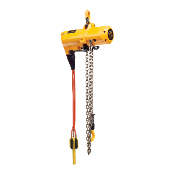
LUBRICANT FREE
AIR POWERED
CHAIN HOIST
TCL SERIES
¼, tonne through 1 tonne Capacity
Code, Lot and Serial Number
WARNING
This equipment should not be installed, operated or
maintained by any person who has not read and understood
all the contents of this manual. Failure to read and comply
with the contents of this manual can result in serious bodily
injury or death, and/or property damage.
Advertisement
Table of Contents

Subscribe to Our Youtube Channel
Related Manuals for KITO TCL Series


Summary of Contents for KITO TCL Series
- Page 1 EFFECTIVE: April 1, 2020 Owner’s Manual LUBRICANT FREE AIR POWERED CHAIN HOIST TCL SERIES ¼, tonne through 1 tonne Capacity Code, Lot and Serial Number WARNING This equipment should not be installed, operated or maintained by any person who has not read and understood all the contents of this manual.
-
Page 2: Table Of Contents
Table of Contents Section Page Number Important Information and Warnings…………………………………………………………………4 Terms and Summary Warning Tags and Labels Technical Information………………………………………………………………………………… 8 Specifications Dimensions Part Names Pre-operational Procedures………………………………………………………………………..13 Air Supply System Requirements Air Supply Capacity And Regulation Lubrication Air Filtration Air Dryer Piping, Hoses And Fittings Exhaust Control Mounting Location... - Page 3 Section Page Number Inspection………………………………………………………………………….………………… 30 General Inspection Classification Preoperation Inspection Frequent Inspection Periodic Inspection Occasionally Used Hoists Inspection Records Inspection Methods and Criteria Lubrication…………………………………………………………………………………………... 38 Air Hoist Lubrication Load Chain Lubrication Hooks and Suspension Components Maintenance & Handling…………………………………………………………………………… 40 Brake Load Chain Pendant Pull Cord...
-
Page 4: Important Information And Warnings
Record your hoist’s Code and Serial Number on the front cover of this manual for identification and future reference to avoid referring to the wrong manual for information or instructions on installation, operation, inspection, maintenance, or parts. Use only KITO authorized replacement parts in the service and maintenance of this hoist. - Page 5 WARNING Equipment described herein is not designed for and MUST NOT be used for lifting, supporting, or transporting people, or for lifting or supporting loads over people. Equipment described herein should not be used in conjunction with other equipment unless necessary and/or required safety devices applicable to the system, crane, or application are installed by the system designer, system manufacturer, crane manufacturer, installer, or user.
- Page 6 ANSI/ASME B30 volume that addresses that type of equipment must also be read by all personnel. If the hoist owner/user requires additional information, or if any information in the manual is not clear, contact KITO or the distributor of the hoist. Do not install, inspect, test, maintain, or operate this hoist unless this information is fully understood.
-
Page 7: Warning Tags And Labels
Warning Tags and Labels The warning tag illustrated below in Figure 1-1 is supplied with each hoist shipped from the factory. If the tag is not attached to your hoist (for pendant control, the warning tag is attached to the pendant hose; for the pull cord control, the warning tag is attached to the up cord), order a tag from your dealer and install it. -
Page 8: Technical Information
2.0 Technical Information Specifications 2.1.1 Product Code 2.1.2 Operating Conditions and Environment Temperature range: -10° to +60°C (+14° to +140°F) Relative Humidity: 85% or less Noise Level: 83 dba maximum @ 1 meter when lifting rated load 93 dba maximum @ 1 meter when lowering rated load Supply Air: 60 to 90 psi (0.4 to 0.6 MPa) Air Consumption:... - Page 9 Table 2-1 Hoist Specifications Load Chain Up/Down Push Weight for Up/Down Speeds Diameter Air Consumption Rates Standard Button Additional Cap. Product (mm) (ft/min @ 90 psi) Lift Hose Weight One foot (cubic ft/min @ 90 psi) tonne Code (ft) (lbs) of Lift Chain Fall (ft)
-
Page 10: Dimensions
Dimensions Table 2-2 TCL with Pendant Control Dimensions Double Fall Hoist Single Fall Hoist Headroom Cap. Product tonne Code (in) (in) (in) (in) (in) (in) (in) (in) (in) TCL250P 16.3 14.4 TCL500P 16.3 14.4 TCL1000P2 18.0 14.4... - Page 11 Table 2-3 TCL with Cord Control Dimensions Double Fall Hoist Single Fall Hoist Headroom Cap. Product tonne Code (in) (in) (in) (in) (in) (in) (in) (in) TCL250C 16.3 14.4 TCL500C 16.3 14.4 TCL1000C2 18.0 14.4 Table 2-4 Top and Bottom Hook Dimension* Units = inch Product Code TCL250C/P...
-
Page 12: Part Names
Part Names Figure 2-1 Hoist Part Identification Diagrams – TCL250C/P and TCL500C/P Figure 2-2 Hoist Part Identification Diagrams – TCL1000C2/P2... -
Page 13: Preoperational Procedures
3.0 Preoperational Procedures Air Supply System Requirements NOTICE 3.1.1 Pressure and Flow - Verify that the air supply system has capacity to supply your air hoist with required pressure and flow. Otherwise the hoist may operate poorly or may fail to operate. -
Page 14: Air Filtration
Air Filtration CAUTION 3.4.1 The air entering the hoist inlet must not contain any particulate greater than 5 microns in size. Therefore, the hoist must have a 5 micron filter in its air supply. If using a lubricator, the filter must be upstream. 3.4.2 The filter servicing the hoist can also service other hoists and air consuming equipment. - Page 15 Figure 3-2 Typical Air Supply Filter with auto drain, Regulator, and Lubricator (if included). NOTICE 3.6.2 Piping - Pipe should be sized to accommodate the hoist airflow requirements. Table 3-1 gives recommended pipe sizes. Table 3-1 Air Supply Pipe and Hose Sizes Model Diameter of Supply Pipe Diameter of Supply Hose...
-
Page 16: Exhaust Control
Figure 3-3 Typical Arrangements of Filter, Regulator and Lubricator and Maximum Air Supply Hose Lengths CAUTION 3.6.4 Fittings - Important considerations regarding fittings in the hoist's air supply include: ◼ When connecting air supply components, remove all dirt or debris from the connecting surfaces of the hoses, pipes, fittings, or threaded fasteners to prevent contaminants from entering the hoist. -
Page 17: Mounting Location
Figure 3-4 Extended Hoist Exhaust Installation Mounting Location WARNING 3.8.1 Prior to mounting the hoist ensure that the suspension and it supporting structure are adequate to support the hoist and its loads. If necessary consult a professional that is qualified to evaluate the adequacy of the suspension location and its supporting structure. -
Page 18: Connecting Hoist To Air Supply
Figure 3-5 Hoist “Secondary Restraint” Configuration NOTICE 3.8.3 See Section 7.7 for outdoor installation considerations. Connecting Hoist to Air Supply WARNING 3.9.1 HAZARDOUS AIR PRESSURE IS PRESENT IN THE HOIST, IN THE SUPPLY OF COMPRESSED AIR TO THE HOIST, AND IN THE CONNECTIONS BETWEEN COMPONENTS. 3.9.2 Shut off the air supply and stop the airflow completely. -
Page 19: Mounting The Hoist
3.9.4 Make connections to air supply; reference Figure 3-6. Use a reducing adapter at the hoist valve section for hose sizes larger than 1/2”. NOTICE 3.9.5 Where conditions dictate, the installation sequence can be reversed by mounting the hoist first followed by connecting the air supply. 3.10 Mounting the Hoist 3.10.1 Manual Trolley - Follow instructions in Owner’s Manual provided with the trolley. -
Page 20: Non-Stationary Application
Figure 3-7 Chain Container Installation 3.12 Non-Stationary Application 3.12.1 For applications such as rental fleets or construction sites where the hoist is moved from place-to- place, a filter and lubricator are still required. Consult factory for recommended methods. 3.12.2 Connections and fittings must be kept clean and care taken to prevent dirt, debris and moisture from entering the hoist. - Page 21 Figure 3-8 Twist in Load Chain Figure 3-9 Capsized Hook and Load Chain WARNING 3.13.3 Ensure the load chain is adequately lubricated according to Section 6.2. WARNING 3.13.4 Confirm the adequacy of the rated capacity for all slings, chains, wire ropes and all other lifting attachments before use.
- Page 22 NOTE: Different Limit Lever TCL250P and TCL500P TCL250C, TCL500C and TCL1000C2/P2 Figure 3-10 Limit Switch Components 3.13.6 Measure and record the “K” dimension of all hooks on hoist. See Table 5-7 under Section 5, “Inspection”. Always use the same side of the hook to measure and record the "K" dimension. 3.13.7 Record the hoist Code Number and Serial Number (from the nameplate on the hoist –...
- Page 23 3.13.16 Proceed with trial operation to confirm proper operation. CAUTION ◼ Make sure hook travel is in the same direction as shown on controls. ◼ Initially operate slowly under no load in both directions. Verify controls agree with hoist direction. Perform inspections per Section 5.4, “Frequent Inspections”.
-
Page 24: Operation
4.0 Operation Introduction DANGER DO NOT WALK UNDER A SUSPENDED LOAD WARNING HOIST OPERATORS SHALL BE REQUIRED TO READ THE OPERATION SECTION OF THIS MANUAL, THE WARNINGS CONTAINED IN THIS MANUAL, INSTRUCTION AND WARNING LABELS ON THE HOIST OR LIFTING SYSTEM, AND THE OPERATION SECTIONS OF ANSI/ASME B30.16 and ANSI/ASME B30.10. THE OPERATOR SHALL ALSO BE REQUIRED TO BE FAMILIAR WITH THE HOIST AND HOIST CONTROLS BEFORE BEING AUTHORIZED TO OPERATE THE HOIST OR LIFTING SYSTEM. -
Page 25: Shall's And Shall Not's For Operation
The operation of an overhead hoist involves more than activating the hoist’s controls. Per the ANSI/ASME B30 standards, the use of an overhead hoist is subject to certain hazards that cannot be mitigated by engineered features, but only by the exercise of intelligence, care, common sense, and experience in anticipating the effects and results of activating the hoist’s controls. -
Page 26: Hoist Controls
CAUTION Improper operation of a hoist can create a potentially hazardous situation which, if not avoided, could result in minor or moderate injury, or property damage. To avoid such a potentially hazardous situation THE OPERATOR SHALL: • • Use the hoist manufacturer’s recommended parts Maintain a firm footing or be otherwise secured when operating the hoist. -
Page 27: Adjusting The Controls
4.3.3 Cord Control - When using a hoist with cord control, pull down on the appropriate colored cord to raise or lower the hoist. White indicates the raise control and red indicates lowering control. Release the cords to stop the hoist. Refer to Figure 4-2 below. Figure 4-2 Cord Control CAUTION 4.3.4... -
Page 28: Speed Adjustment Controls
Speed Adjustment Controls 4.5.1 The hoist is equipped with speed adjustment controls. The controls allow the hoist lifting and lowering speeds to be reduced for those applications requiring slower speeds or better speed control. The speed adjustment controls are set for the highest speed from the factory. The speed adjustment controls are located on top of the valve section of the hoist as shown in Figure 4-4. -
Page 29: Pendant Controllability Adjustment
Pendant Controllability Adjustment 4.6.1 The standard pendant hose length is 8.1 feet. For pendant hose lengths beyond 16 feet, the speed controllability from the pendant may be diminished. The reduction in speed control is a result of pressure loss due to the longer pendant hose. The pendant hose extension adjustment control provides a screw adjustment method to reduce the air pressure loss to provide normal pendant/hoist operation. -
Page 30: Inspection
5.0 Inspection General 5.1.1 The inspection procedure herein is based on ANSI/ASME B30.16. The following definitions are from ANSI/ASME B30.16 and pertain to the inspection procedure below. ◼ Designated Person - a person selected or assigned as being competent to perform the specific duties to which he/she is assigned. -
Page 31: Preoperation Inspection
◼ Heavy service - semiannually ◼ Severe service - quarterly ◼ Special or infrequent service - as recommended by a qualified person before the first such occurrence and as directed by the qualified person for any subsequent occurrences. Preoperation Inspection 5.3.1 The preoperational inspection shall be performed before the first use of each shift in accordance with Table 5-1, “Preoperation Inspection”. -
Page 32: Occasionally Used Hoists
5.5.2 For inspections where load suspension parts of the hoist are disassembled, a load test per ANSI/ASME B30.16 must be performed on the hoist after it is re-assembled and prior to its return to service. Table 5-3 Periodic Inspection Requirements of frequent inspection. Evidence of loose bolts, nuts, or rivets. - Page 33 Table 5-4 Hoist Inspection Methods and Criteria Item Method Criteria Action Functional operating Visual, Auditory Mechanisms should be properly adjusted and Repair or replace mechanisms. should not produce unusual sounds when as required. operated. Limit Lever Function Proper operation. Actuation of limit lever should Repair or replace stop hoist.
- Page 34 Table 5-4 Hoist Inspection Methods and Criteria Item Method Criteria Action Replace. Load Chain - Visual Should be free of rust, nicks, gouges, dents, and Surface Condition weld spatter. Links should not be deformed, and should not show signs of abrasion. Surfaces where links bear on one another should be free of significant wear.
- Page 35 Table 5-4 Hoist Inspection Methods and Criteria Item Method Criteria Action Pendant - Housing Visual Pendant housing should be free of cracks and Replace. mating surfaces of parts should seal without gaps. Pendant - Tubing Visual, auditory Tubing to pendant control switches should not be Repair or replace loose or be leaking air.
- Page 36 Table 5-6 Chain Separator Dimensions Std Dimension Maximum Value for Replacement Parts View Hoists Figure No. Inch (mm) Inch (mm) TCL250C2/P2 L = 0.51 (13) L = 0.63 (16) TCL500C2/P2 W = 0.95 (24) W = 1.04 (26.5) TCL1000C2/P2 Table 5-7 Top Hook & Bottom Hook Dimensions Dimensions K and U should be measured and recorded below prior to any use when the hook is first placed into service.
- Page 37 Table 5-8 Top Hook/Yoke Gap Wear Limit Dimension Minimum Value for Replacement Capacity Code Parts View Item No. Inch (mm) TCL250C2/P2 TCL500C2/P2 140A 0.1 inch (7/64)/2.5mm. TCL1000C2/P2 Table 5-9 Chain Dimensions “P” Dimension “d” Dimension Parts View inch (mm) inch (mm) Product Code Figure No.
-
Page 38: Lubrication
6.2.3 Apply KITO lubricating grease (Part No. ER1BS1951) or an equivalent to industrial general lithium grease, NLGI No. 0, to the bearing surfaces of the load chain links as indicated by the shaded areas in Figure 6-1. Also apply the grease to the areas of the load chain that contact the load sheave. Ensure that the grease is applied to the contact areas in the load sheave pockets. - Page 39 Part Location Lubrication Grade ISO VG 32-56 or Air motor, if lubricated Lubricator Turbine Oil equivalent - KITO Chain Grease P/N ER1BS1551 Load chain & pocket Grease, Machine or Load Chain - NLGI No. 0 wheel gear oil - ISO VG 46-68 or equivalent Hook bearings &...
-
Page 40: Maintenance & Handling
7.0 Maintenance and Handling Brake 7.1.1 The hoist brake is not adjustable. 7.1.2 Inspect the brake disc in accordance with Section 5.7, Table 5-5. 7.1.3 The following is the hoist brake inspection procedure. Refer to Figure 7-1. WARNING HAZARDOUS AIR PRESSURE IS PRESENT IN THE HOIST, IN THE SUPPLY OF COMPRESSED AIR TO THE HOIST, AND IN THE CONNECTIONS BETWEEN COMPONENTS. -
Page 41: Load Chain
WARNING Be certain that the replacement chain is obtained from KITO and is the exact size, grade and construction as the original chain. The new load chain must have an even number of links so that the end links are oriented 90° from each other. - Page 42 After installation has been completed, perform steps outlined in Section 3.13 "Preoperational Checks and Trial Operation". Figure 7-3 Load Chain Installation Diagram...
- Page 43 Figure 7-4 Single Fall Chain Connections Figure 7-5 Double Fall Chain Connections...
-
Page 44: Pendant
Pendant 7.3.1 The following procedure covers the installation of the Pendant Hose (Parts List Figure Number 360) and the Pendant Valve. Refer to Figure 7-6. 1) Place boot on the ends of the Pendant Hoses to be attached to the Manifold Block on the hoist. 2) Attach pendant hose to hoist body using the one-piece fittings and screw type clamps (hose bands). -
Page 45: Pull Cord
Pull Cord 7.4.1 The following procedure covers the installation of the Pull Cord (Parts List Figure Number 401) and the Handles. Refer to Figure 7-7. Chain Lever is attached to the Limit Shaft on the hoist. Ensure the WHITE Handle is attached to the UP, Chain Lever side and the RED Handle is attached to the DOWN Chain Lever side. -
Page 46: Load Sheave Inspection
Load Sheave Inspection 7.5.1 Perform this inspection by removing the chain separator (lower chain guide) and viewing the load sheave while operating the hoist slowly, with no load, and in accordance with Section 4 “Operation”. Refer to Figure 7-8 and remove the chain separator as follows: CAUTION An air supply line must be connected to the hoist in order to perform the following procedures. -
Page 47: Storage
Storage 7.6.1 Whenever the hoist is to be placed into storage, place extra, at least 3cc, lubricating oil into the air inlet opening and circulate the air motor before plugging the inlet. Make certain that no debris, dirt or moisture is allowed to enter the air hoist through air inlet opening during preparations for storage. 7.6.1 The storage location should be clean and dry. -
Page 48: Troubleshooting
8.0 Troubleshooting WARNING HAZARDOUS AIR PRESSURE IS PRESENT IN THE HOIST, IN THE SUPPLY OF COMPRESSED AIR TO THE HOIST, AND IN CONNECTIONS BETWEEN COMPONENTS. Before performing ANY maintenance on the equipment, de-energize the supply of compressed air to the equipment, and lock and tag the supply device in the de-energized position. - Page 49 Table 8-1 Troubleshooting Guide (continued) Symptom Cause Remedy Hoist is overloaded. Reduce load to hoist rated capacity. Faulty pendant control or control Repair or replace pendant control or Hoist lowers but will not lift hose(s) control hose(s) Lack of air pressure or partial loss of Repair or adjust air supply or filters.
-
Page 50: Warranty
9.0 Warranty All products sold by KITO Canada Inc. are warranted to be free from defects in material and workmanship from date of purchase for the following periods: 1 year – Hoists, Trolleys and Parts 3 years – ER2, EQ and SEQ Model Hoists 5 years –... -
Page 51: Parts Information
10.0 Parts Information A complete parts list is supplied with your hoist and when ordering Parts, please provide the Hoist code number located on the Hoist nameplate (see Figure 10-1 below). To aid in ordering Parts and Product Support, record the Hoist code number and serial number in the space provided on the cover of this manual. -
Page 52: Motor, Valve Body And Controls
10.1 Motor, Valve Body and Controls Figure 10-1 Motor, Valve Body and Controls... - Page 53 10.1 Motor, Valve Body and Controls Parts Parts Figure Figure Name Part Number Name Part Number Number Number hoist hoist Throttle Valve T1CR420215VB0 Spring Pin (4X16) T1CS130604016 Valve Bushing (Up) T1CS426230E90 Spring Pin (3X5) T1CS130603005 Valve Bushing (Down) T1CS426230F00 Retaining Ring (S-15) M3S153-010S Spring Seat T1CS426230C70...
- Page 54 10.1 Motor, Valve Body and Controls Parts Figure Name Part Number Number hoist Pendant Hose 3@FT T1CR137240926 Strain Relief Wire T1CR230708005 Hose Fitting (H-1 PT1/8-7) T1CS135106301 Hose Clamp T1CR137501012 Socket Bolt (HSHCS M5X10) T1CS131705010 Washer (M5) T1CS131307005...
- Page 55 This Page Intentionally Left Blank...
-
Page 56: Brake, Gears And Load Suspension Components
10.2 Brake, Gears and Load Suspension Components Figure 10-2 Brake, Gears and Load Suspension Components... - Page 57 10.2 Brake, Gears and Load Suspension Components Parts Parts Figure Figure Name Part Number Name Part Number Number Number hoist hoist Center Housing T1CS426230A00 O-Ring (S-8) T1CS131103006 Load Sheave T1CS426230A50 O-Ring (S-90) T1CS131103052 Coupling T1CS426230200 Spring Pin (3X14) T1CS130603014 Chain Guide T1CS426230350 Spring Pin (6X15) T1CS130606015...
- Page 58 10.2 Brake, Gears and Load Suspension Components TCL 1000 Top Hook Assembly TCL 1000 Lower Hook Assembly Parts Parts Figure Figure Name Part Number Name Part Number Number Number hoist hoist Top Hook T1CR426261S20 Swivel Bottom Hook T1CS426261S20 Hook Latch T1CR426221BK0 Hook Latch T1CR426221BK0...
-
Page 59: Rebuild Kits
10.3 Rebuild Kits TCL Hoist Rebuild Parts Parts per hoist Figure T1CS426331D5D T1CS426335D5D Cord Name Part Number Number Pendant Controlled Controlled Hoist Hoist Rebuild Kit Rebuild Kit Silencer (S) T1CS137402023 Valve Gasket T1CS136102165 O-Ring (S-7) T1CR131103005 O-Ring (S-15) T1CR131103013 O-Ring (S-20) T1CR131103016 O-Ring (S-22) T1CR131103017... -
Page 60: Chain Container Assembly
10.4 Chain Container Assembly Figure 10-4 Chain Container Assembly (optional) Parts Figure Name Part Number Number hoist Chain Container Assembly T1CS42623055C Socket Bolt T1CS426230F40 Flat Washer T1CR131307008 Hex Nut T1CR134401008 Split Pin (2.5x20) T1CS130702120 Socket Bolt T1CS426230F50 Flat Washer T1CR131307006 Hex Nut T1CR134403006 Split Pin (2x15) - Page 61 NOTES...
- Page 62 NOTES...
- Page 63 NOTES...
- Page 64 KITO Canada Inc. West KITO Canada Inc. East 309-3815 1 Avenue 6-1750 Courtney Park Drive E. Burnaby, BC V5C 3V6 Mississauga, ON L5T 1W1 Phone: 604-291-9955 Phone: 905-405-0905 Toll Free: 1-888-322-KITO Toll Free: 1-888-322-KITO Fax: 604-294-8855 Fax: 905-405-0906 www.kito.ca...
Need help?
Do you have a question about the TCL Series and is the answer not in the manual?
Questions and answers