Table of Contents
Advertisement
Quick Links
EFFECTIVE: April 28, 2020
Owner's Manual
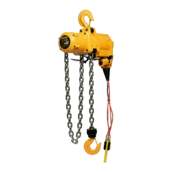
AIR
POWERED
CHAIN HOIST
TCK SERIES
3 Ton and 6 Ton Capacity
Code Number and Serial Number
WARNING
This equipment should not be installed, operated or
maintained by any person who has not read and understood
all the contents of this manual. Failure to read and comply
with the contents of this manual can result in serious bodily
injury or death, and/or property damage.
© Harrington Hoists, Inc.
All Rights Reserved
Advertisement
Table of Contents

Related Manuals for KITO Harrington TCK Series


Summary of Contents for KITO Harrington TCK Series
- Page 1 EFFECTIVE: April 28, 2020 Owner’s Manual POWERED CHAIN HOIST TCK SERIES 3 Ton and 6 Ton Capacity Code Number and Serial Number WARNING This equipment should not be installed, operated or maintained by any person who has not read and understood all the contents of this manual.
-
Page 2: Table Of Contents
Table of Contents Section Page Number Important Information and Warnings…………………………………………………………………4 Terms and Summary Warning Tags and Labels Technical Information………………………………………………………………………………… 8 Specifications Dimensions Part Names Pre-operational Procedures………………………………………………………………………... 12 Air Supply System Requirements Air Supply Capacity and Regulation Lubrication Filtration Air Dryer Piping, Hoses and Fittings Mounting Location Connecting Hoist to Air Supply... - Page 3 Section Page Number Inspection……………………………………………………………………………………………. 28 General Inspection Classification Frequent Inspection Periodic Inspection Occasionally Used Hoists Inspection Records Inspection Methods and Criteria Lubrication…………………………………………………………………………………………... 36 Air Hoist Lubrication Load Chain Lubrication Hooks and Suspension Components Maintenance & Handling…………………………………………………………………………… 38 Load Limiter Brake Load Chain Pendant Load Sheave Inspection...
-
Page 4: Important Information And Warnings
Important Information and Warnings Terms and Summary This manual provides important information for personnel involved with the installation, operation and maintenance of this product. Although you may be familiar with this or similar equipment, it is strongly recommended that you read this manual before installing, operating or maintaining the product. - Page 5 WARNING Equipment described herein is not designed for and MUST NOT be used for lifting, supporting, or transporting people, or for lifting or supporting loads over people. Equipment described herein should not be used in conjunction with other equipment unless necessary and/or required safety devices applicable to the system, crane, or application are installed by the system designer, system manufacturer, crane manufacturer, installer, or user.
- Page 6 DANGER HAZARDOUS AIR PRESSURE IS PRESENT IN THE HOIST, IN THE SUPPLY OF COMPRESSED AIR TO THE HOIST, AND IN THE CONNECTIONS BETWEEN COMPONENTS. Before performing ANY maintenance on the equipment, de-energize the supply of compressed air to the equipment, and lock and tag the supply device in the de-energized position. Refer to ANSI Z244.1, “Personnel Protection - Lockout/Tagout of Energy Sources.”...
-
Page 7: Warning Tags And Labels
Warning Tags and Labels The warning tag illustrated below in Figure 1-1 is supplied with each hoist shipped from the factory. If the tag is not attached to your hoist (for pendant control, the warning tag is attached to the pendant hose; for the pull cord control, the warning tag is attached to the up cord), order a tag from your dealer and install it. -
Page 8: Technical Information
2.0 Technical Information Specifications 2.1.1 Product Code 2.1.2 Operating Conditions and Environment Temperature range: -4° to +158°F (-20° to +70°C) Relative Humidity: 85% or less Noise Level: 84 dba maximum @ 1 meter when lifting/lowering rated load Supply Air: 60 to 90 pounds per square inch Air Consumption: 30 to 90 cubic feet minute Air Lubrication Requirements:... -
Page 9: Dimensions
Table 2-1 Hoist Specifications Push Up/Down Load Chain Up/Down Speeds Weight for Button Air Consumption Rates Diameter Standard Additional (ft/min @ 90 psi) Cap. Product Hose or (mm) (cubic ft/min @ 90 psi) Lift Weight One Foot (Tons) Code Cord (ft) (lbs) of Lift... - Page 10 Table 2-3 TCK with Cord Control Dimensions Single Fall Hoist Double Fall Hoist Headroom Cap. Product (Tons) Code (in) (in) (in) (in) (in) (in) (in) (in) (in) TCK3000C 21.1 22.7 12.4 10.4 12.2 TCK6000C2 30.3 22.7 14.6 10.4 12.2 Table 2-4 Top and Bottom Hook Dimension* Units = inch Product Code TCK3000...
-
Page 11: Part Names
Part Names Figure 2-1 Hoist Part Identification Diagrams TCK3000 Figure 2-2 Hoist Part Identification Diagrams TCK6000... -
Page 12: Preoperational Procedures
3.0 Preoperational Procedures Air Supply System Requirements NOTICE Pressure and Flow – Verify that the air supply system has capacity to supply your 3.1.1 air hoist with required pressure and flow. Otherwise the hoist may operate poorly or may fail to operate. -
Page 13: Filtration
Filtration CAUTION 3.4.1 The air entering the hoist inlet must not contain any particulate greater than 5 microns in size. Therefore, the hoist must have a 5 micron filter in its air supply. The filter must be upstream of the lubricator. 3.4.2 The filter servicing the hoist can also service other hoists and air consuming equipment. - Page 14 Figure 3-2 Typical Air Supply Filter, Regulator and Lubricator. NOTICE Piping – Pipe should be sized to accommodate the hoist airflow requirements. 3.6.2 Table 3-1 gives recommended pipe sizes. Table 3-1 Air Supply Pipe and Hose Sizes Model Diameter of Supply Pipe Diameter of Supply Hose Inside diameter Inside diameter...
- Page 15 Figure 3-3 Typical Arrangements of Filter, Regulator and Lubricator and Maximum Air Supply Hose Lengths CAUTION Fittings – Important considerations regarding fittings in the hoist's air supply 3.6.4 include: ◼ When connecting air supply components, remove all dirt or debris from the connecting surfaces of the hoses, pipes, fittings, or threaded fasteners to prevent contaminants from entering the hoist.
-
Page 16: Mounting Location
Figure 3-4 Extended Hoist Exhaust Installation Mounting Location WARNING 3.8.1 Prior to mounting the hoist ensure that the suspension and its supporting structure are adequate to support the hoist and its loads. If necessary consult a professional that is qualified to evaluate the adequacy of the suspension location and its supporting structure. For applications requiring a “Secondary Support”... -
Page 17: Connecting Hoist To Air Supply
TCK3000 TCK6000 Figure 3-5 Hoist “Secondary Support” Configuration NOTICE 3.8.3 See Section 7.7 for outdoor installation considerations. 3.9 Connecting Hoist to Air Supply WARNING 3.9.1 HAZARDOUS AIR PRESSURE IS PRESENT IN THE HOIST, IN THE SUPPLY OF COMPRESSED AIR TO THE HOIST, AND IN THE CONNECTIONS BETWEEN COMPONENTS. Figure 3-6 Typical Air Supply Connection 3.9.2 Shut off the air supply and stop the airflow completely. -
Page 18: Optional Chain Container
3.10.3 Hook Mounted to a Fixed Location – Attach the hoist’s top hook to the fixed suspension point. WARNING Ensure that the fixed suspension point rests on the center of the hook’s saddle 3.10.4 and that the hook’s latch is engaged . 3.11 Optional Chain Container 3.11.1 For installation of the optional bag style chain container refer to Figure 3-7 and perform the following:... -
Page 19: Non-Stationary Application
Figure 3-7 Optional Chain Container Installation 3.12 Non-Stationary Application 3.12.1 For applications such as rental fleets or construction sites where the hoist is moved from place-to- place, a filter and lubricator are still required. Consult factory for recommended methods. 3.12.1 Connections and fittings must be kept clean and care taken to prevent dirt, debris and moisture from entering the hoist. -
Page 20: Preoperational Checks And Trial Operation
3.13 Preoperational Checks and Trial Operation CAUTION 3.13.1 Check for the availability of required operating air pressure of between 60 PSI to 90 PSI at the hoist's inlet port before trying to operate the hoist. WARNING 3.13.2 Verify that the load chain is not twisted or tangled and that the bottom hook is not capsized prior to operating the hoist. - Page 21 TCK3000 and TCK6000 Figure 3-10 Limit Switch Components 3.13.5 For Models TCK3000 and TCK6000 verify that the chain/limit lever is operational and can move freely in both the up and down directions. 3.13.6 Measure and record the “K” dimension of all hooks on hoist. See Table 5-6 under Section 5, “Inspection”.
- Page 22 CAUTION 3.13.13 Check the lubricator for proper function and adequate oil level. 3.13.14 Confirm proper operation. ◼ Before operating read and become familiar with Section 4 - Operation. ◼ Before operating ensure that the hoist (and trolley) meets the Inspection, Testing and Maintenance requirements of ANSI/ASME B30.16.
-
Page 23: Operation
Operation Introduction DANGER DO NOT WALK UNDER A SUSPENDED LOAD WARNING HOIST OPERATORS SHALL BE REQUIRED TO READ THE OPERATION SECTION OF THIS MANUAL, THE WARNINGS CONTAINED IN THIS MANUAL, INSTRUCTION AND WARNING LABELS ON THE HOIST OR LIFTING SYSTEM, AND THE OPERATION SECTIONS OF ANSI/ASME B30.16 and ANSI/ASME B30.10. THE OPERATOR SHALL ALSO BE REQUIRED TO BE FAMILIAR WITH THE HOIST AND HOIST CONTROLS BEFORE BEING AUTHORIZED TO OPERATE THE HOIST OR LIFTING SYSTEM. -
Page 24: Shall's And Shall Not's For Operation
The operation of an overhead hoist involves more than activating the hoist’s controls. Per the ANSI/ASME B30 standards, the use of an overhead hoist is subject to certain hazards that cannot be mitigated by engineered features, but only by the exercise of intelligence, care, common sense, and experience in anticipating the effects and results of activating the hoist’s controls. -
Page 25: Hoist Controls
CAUTION Improper operation of a hoist can create a potentially hazardous situation which, if not avoided, could result in minor or moderate injury, or property damage. To avoid such a potentially hazardous situation THE OPERATOR SHALL: • • Use the hoist manufacturer’s recommended parts Maintain a firm footing or be otherwise secured when operating the hoist. - Page 26 Pendant used with Optional E-Stop Pendant used with 10mm X 6.3mm Hose 10mm X 6.3mm Hose Figure 4-1 Pendant Control Cord Control – When using a hoist with cord control, pull down on the appropriate colored cord to raise 4.3.3 or lower the hoist.
-
Page 27: Adjusting The Controls
Adjusting the Controls 4.4.1 For pendant control, the speed can be adjusted by the amount the lever is depressed. As shown below in Figure 4-3, by depressing the lever slightly, you will be able control the hoist’s motions slowly and with more precision. -
Page 28: Inspection
Inspection General 5.1.1 The inspection procedure herein is based on ANSI/ASME B30.16. The following definitions are from ANSI/ASME B30.16 and pertain to the inspection procedure below. Designated Person – person selected or assigned as being competent to perform the specific ◼... -
Page 29: Frequent Inspection
Frequent Inspection Inspections should be made on a FREQUENT basis in accordance with Table 5-1, “Frequent 5.3.1 Inspection.” Included in these FREQUENT Inspections are observations made during operation for any defects or damage that might appear between Periodic Inspections. Evaluation and resolution of the results of FREQUENT Inspections shall be made by a designated person such that the hoist is maintained in safe working condition. -
Page 30: Occasionally Used Hoists
Occasionally Used Hoists 5.5.1 Hoists that are used infrequently shall be inspected as follows prior to placing in service: ◼ Hoist Idle More Than 1 Month, Less Than 1 Year: Inspect per FREQUENT Inspection criteria of Section 5.3. ◼ Hoist Idle More Than 1 Year: Inspect per PERIODIC Inspection criteria of Section 5.4. Inspection Records 5.6.1 Dated inspection reports and records should be maintained at time intervals corresponding to those... - Page 31 Table 5-3 Hoist Inspection Methods and Criteria Item Method Criteria Action Hooks - Bent Shank Shank and neck portions of hook should be free Visual Replace. or Neck of deformations Should be free of significant rust, weld splatter, Hooks - Yoke nicks, and gouges.
- Page 32 Table 5-3 Hoist Inspection Methods and Criteria Item Method Criteria Action Chain springs should not be deformed or Chain Springs Visual Replace compressed. Chain Container Container should not be damaged. Brackets Visual Replace (optional) should not be deformed or missing. Bolts, Nuts and Visual, Check Tighten or replace...
- Page 33 Table 5-4 Brake Disc Dimensions Std Dimension Minimum Value for Replacement Hoists Inch (mm) Inch (mm) T = 0.31 (8) T = 0.29 (7.3) TCK3000, TCK6000 W = 0.10 (2.6) W = 0.11 (2.8) Table 5-5 Chain Separator Dimensions Std Dimension Maximum Value for Replacement Hoists Inch (mm)
- Page 34 Table 5-6 Top Hook & Bottom Hook Dimensions Dimensions K and U do not have a controlled tolerance; therefore they should be measured and recorded below prior to the hoist being placed into service. The measured K and U values will be the dimensional reference for hook inspection. Parts View Recorded Dimension Maximum/Minimum Value...
- Page 35 Table 5-8 Chain Wear Dimensions “P” Dimension “d” Dimension inch (mm) inch (mm) Capacity Code Standard Discard Standard Discard TCK3000, TCK6000 7.52 (191) 7.74 (196.7) 0.49 (12.5) 0.44 (11.3) Table 5-9 Hook Joint Bolt Dimension Wear Limit Capacity Code Minimum Value for Replacement inch (mm) TCK6000 0.004 (0.1)
-
Page 36: Lubrication
Lubrication Air Hoist Lubrication 6.1.1 See Section 3.0 for lubrication requirements. CAUTION 6.1.2 Lubrication to the motor will be provided primarily by the air supply lubricator. The recommended amount is 10-15 drops/minute (0.2-0.3 cc/min). Refer to Table 6-1 below for the approved lubricant for use with your air hoist. - Page 37 Table 6-1 Table of Approved Lubricants Application Part Location Lubrication Grade ISO VG 32-56 or Air motor Lubricator Turbine Oil equivalent - HHI Chain Grease P/N ER1BS1551 Load chain & pocket Grease or - NLGI No. 0 Load chain wheel Machine/gear oil - ISO VG 32, 46, 68 or equivalent...
-
Page 38: Maintenance & Handling
Maintenance and Handling Load Limiter 7.1.1 The purpose of the load limiter is to prevent using the hoist in an overload situation. When lifting, the hoist will stop automatically if the load is above the rated capacity of the hoist. 7.1.2 The adjustment is factory set to actuate at approximately 125% of rated capacity (based on supply air pressure of 90 PSI). -
Page 39: Brake
Put a load equal to the desired actuation point on the hoist's hook (do not exceed 125% of the hoist's rated capacity). Begin to slowly lift the load, and then increase the lifting speed. Return the load to its resting position so the load chain is not under tension. If the load limiter prevents lifting, turn the adjustment screw IN one full turn. - Page 40 Figure 7-3 Hex Socket Set Screw Removal Remove the Brake Cover, Brake Piston, and Springs from the Gear Case, as shown in Figure 7-4. Figure 7-4 Brake Internals Removal Remove the O-ring from the Brake Piston as shown in Figure 7-5. If the Brake Piston has any cracking, it must be replaced.
-
Page 41: Load Chain
Remove the Brake Disc, as shown in Figure 7-6. Measure the thickness of the Brake Disc and the width of the center splines according to Table 5-4. Prior to reassembly, clean all surfaces of debris, dirt and loose paint. Apply a light film of grease to all O-Ring seals. - Page 42 again while gradually operating hoist controls. Continue until a sufficient quantity of Chain is fed through the hoist to attach the Bottom Hook Complete Set. Ensure that of the Chain remains free of twists and attach the no-load end of the chain to the hoist body with the Flat Washer and Button Head Screw.
- Page 43 Figure 7-8 Single Fall Chain Connections Figure 7-9 Double Fall Chain Connections...
-
Page 44: Pendant
Pendant 7.3.1 The following procedure covers the installation of the Pendant Hose (Parts List Figure Number 360) and the Pendant Valve. Refer to Figure 7-10. 1) Place boot on the ends of the Pendant Hoses to be attached to the Manifold Block on the hoist. 2) Attach pendant hose to hoist body using the one-piece fittings and screw type clamps (hose bands). -
Page 45: Storage
CAUTION An air supply line must be connected to the hoist in order to perform the following procedures. 2) Remove 4 Socket Bolts attaching the Chain Separator to the Wheel Housing and drop the Chain Separator down. 3) Inspect the Load Sheave. Refer to “Load Sheave” in Table 5-3, “Hoist Inspection Methods and Criteria”. - Page 46 Operational Environment 7.8.1 Non-conforming environment A non-conforming environment is defined as one with any or all of the following. • Explosive gases or vapor. • Organic solvents or volatile powder • Excessive amounts of powder and dust of general substances •...
-
Page 47: Troubleshooting
Troubleshooting WARNING HAZARDOUS AIR PRESSURE IS PRESENT IN THE HOIST, IN THE SUPPLY OF COMPRESSED AIR TO THE HOIST, AND IN CONNECTIONS BETWEEN COMPONENTS. Before performing ANY maintenance on the equipment, de-energize the supply of compressed air to the equipment, and lock and tag the supply device in the de-energized position. Refer to ANSI Z244.1, “Personnel Protection - Lockout/Tagout of Energy Sources.”... - Page 48 Table 8-1 Troubleshooting Guide Symptom Cause Remedy Pendant control hoses are Hoist moving in wrong Connect the control hose(s) in terminated to incorrect ports on hoist direction (pendant control) accordance with Section 7.4. body. Hoist is overloaded. Reduce load to hoist rated capacity. Faulty pendant control or control Repair or replace pendant control or Hoist lowers but will not lift...
-
Page 49: Warranty
Warranty Warranty explanation and terms. All products sold by Harrington Hoists, Inc. are warranted to be free from defects in material and workmanship from date of shipment by Harrington for the following periods: 1 year – Electric and Air Powered Hoists (excluding (N)ER2 Enhanced Features Models, EQ / SEQ Hoists), Powered Trolleys, Powered Tiger Track Jibs and Gantries, Crane Components, Spare / Replacement Parts, Below-the-Hook and Material Handling Equipment... -
Page 50: Parts List
10.0 Parts List A complete parts list is available from Harrington Hoists and is supplied separately with your hoist. The parts list is also available from Harrington's web site (www.harringtonhoists.com) or from any Harrington facility (see back cover of this manual). -
Page 51: Motor, Valve Body And Controls
10.1 Motor, Valve Body and Controls... - Page 52 10.1 Motor, Valve Body and Controls Parts Parts Figure Figure Name Part Number Name Part Number Number Number hoist hoist Throttle Valve TCK425806J80 Hex Socket Head Cap Bolt 9091294 (M10X 25) Valve Bushing (Up) TCK425806E90 Set Screw Hex (M8X12) TCK131708012 Valve Bushing (Down) TCK425806F00 Hex Socket Cap Screw...
- Page 53 10.1 Motor, Valve Body and Controls Hex Plug (PT1/8 IN.) TCR134902003 Under Cover TCK425806470 Pilot Silencer TCK137402060 Hex Socket Head Cap Bolt 9091224 (M5X8) Hex Screw (M5X22) TCK132105022 Hex Set Screw (M5X5) 90005843 Cross Head Flat Machine TCK132905206 Screw (M5X6) Hex Nut (M5) TCK134403205 O-Ring (S-29)
-
Page 54: Brake, Gears And Load Suspension Components
10.2 Brake, Gears and Load Suspension Components... - Page 55 10.2 Brake, Gears and Load Suspension Components Figure Parts Figure Parts Name Part Number Name Part Number Number per hoist Number per hoist Center Housing TCK425807A00 Needle Bearing (TA1616Z) TCK130131617 Load Sheave TCK425807A50 Needle Bearing (TA1512Z) TCK130131513 Coupling TCK425806200 HSHCS (M10X25) 9091294 Chain Guide TCK425807350...
- Page 56 10.2 Brake, Gears and Load Suspension Components Figure Parts Name Part Number Number per hoist HSHCS TCK3000 90912117 (M12X45) Under Hook TCK6000 TCK420890QH0 Metal Cover Hex Nut (M12) TCK3000 9093433 Thrust Bearing TCK6000 9000611 (6211ZZ) Spring Washer TCK3000 9012713 (M12) Thrust Bearing TCK6000 TCK130121112...
-
Page 57: Chain Container Assembly
10.3 Chain Container Assembly Figure 10-3 Chain Container Assembly (Optional) Parts Figure Name Part Number Number hoist Chain Container Assembly TCK42580655C... -
Page 58: Hoist Maintenance Kits
10.4 Hoist Maintenance Kits TCK3000/6000 Air Motor Maintenance Kit No. AH0002010: Parts Figure Name Part Number Number hoist Pilot Silencer (SS) TCK137402055 Silencer (SL) TCK137402056 Silencer (F) TCK137402057 Valve Gasket TCK136102171 Vane TCK137102036 Vane/Lift Spring TCR130802235 Air Motor Gasket TCK136102172 Silencer M CP TCK425806K0B Bearing (6010) - Page 59 This Page Intentionally Left Blank...
- Page 60 Harrington Hoists, Inc. Toll Free: 800-233-3010 www.harringtonhoists.com 401 West End Avenue Phone: 717-665-2000 Manheim, PA 17545 Fax: 717-665-2861 © HARRINGTON HOISTS, INC., ALL RIGHTS RESERVED TCKOM...
Need help?
Do you have a question about the Harrington TCK Series and is the answer not in the manual?
Questions and answers