Table of Contents
Advertisement
Quick Links
Advertisement
Chapters
Table of Contents

Related Manuals for Endress+Hauser analytikjena PlasmaQuant 9100


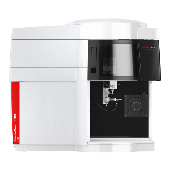
Summary of Contents for Endress+Hauser analytikjena PlasmaQuant 9100
- Page 1 Operating Manual PlasmaQuant 9100 (Elite) High-Resolution Array ICP-OES...
- Page 2 Manufacturer Analytik Jena AG Konrad-Zuse-Straße 1 07745 Jena / Germany Telephone: +49 3641 77 70 Fax: +49 3641 77 9279 E-mail: info@analytik-jena.de Technical Service Analytik Jena AG Konrad-Zuse-Straße 1 07745 Jena / Germany Phone: +49 3641 77 7407 Fax: +49 3641 77 9279 Email: service@analytik-jena.com For a proper and safe use of this product follow the instructions.
-
Page 3: Table Of Contents
PlasmaQuant 9100 (Elite) Table of contents Table of contents 1 Basic information................................About this user manual ............................ Intended use ..............................2 Security .................................... Safety labeling on the device ........................... Requirements for the operating personnel..................... Safety instructions, transport and commissioning ..................Safety instructions: during operation ...................... - Page 4 Table of contents PlasmaQuant 9100 (Elite) 4.4.3 Installing the argon humidifier ........................43 4.4.4 Installing the inline filter..........................44 5 Operation ..................................45 Switching on the emission spectrometer and igniting the plasma..............45 Switching off the emission spectrometer......................46 Switching off the device via the plasma deactivation switch in an emergency ..........47 Starting a measurement routine........................
-
Page 5: Basic Information
PlasmaQuant 9100 (Elite) Basic information Basic information About this user manual Contents This user manual describes the following device models: ¡ PlasmaQuant PQ 9100 ¡ PlasmaQuant PQ 9100 Elite In this following, these models are collectively referred to as PlasmaQuant PQ 9100. Any differences between the models are explained in the corresponding section. -
Page 6: Intended Use
Basic information PlasmaQuant 9100 (Elite) Intended use The ICP Emission Spectrometer (ICP-OES) is used in a chemical analysis laboratory for the analysis of liquid - mainly aqueous - samples to determine the concentrations of up to 75 elements up to the trace range. The device and its components may only be used for the analyses listed in the user man- ual. -
Page 7: Security
PlasmaQuant 9100 (Elite) Security Security For your own safety and to ensure error-free and safe operation of the device, please read this chapter carefully before commissioning. Observe all safety instructions listed in this user manual and all messages and infor- mation displayed on the monitor by the control and analysis software. -
Page 8: Requirements For The Operating Personnel
Security PlasmaQuant 9100 (Elite) Notice symbol Meaning Comment People' s Republic of This device contains controlled sub- China only: stances. Analytik Jena guarantees that these substances will not escape the de- vice in the next 25 years if operated in accordance with its intended purpose. -
Page 9: Safety Instructions: During Operation
PlasmaQuant 9100 (Elite) Security The decontamination report is available from Service when registering the re- turn. Service must refuse acceptance of contaminated devices. The sender may be liable for damage caused by inadequate decontamination of the device. Safety instructions: during operation 2.4.1 Basic safety information for operation The operator must make sure that the device and its safety equipment is in sound... -
Page 10: Hazards Caused By Plasma Operation
Security PlasmaQuant 9100 (Elite) The power plug must be connected to a proper power outlet to ensure that the ¡ device meets protection class I (ground connector). The device may only be con- nected to power sources whose nominal voltage is the same as that on the rating plate. -
Page 11: Safety Instructions On The Formation Of Ozone And Toxic Vapors
PlasmaQuant 9100 (Elite) Security 2.4.6 Safety instructions on the formation of ozone and toxic vapors The interaction between the UV radiation from the torch and the surrounding air re- sults in the formation of a high concentration of toxic gases such as ozone and nitro- gen oxides. -
Page 12: Safety Instructions On Cleaning And Decontamination Measures
Security PlasmaQuant 9100 (Elite) 2.4.9 Safety instructions on cleaning and decontamination measures Observe the following: The operator is responsible for carrying out suitable decontamination should the ¡ device become contaminated externally or internally with dangerous substances. ¡ Splashes, drops or larger liquid spillages should be removed using an absorbent material such as cotton wool, laboratory wipes or cellulose. -
Page 13: Function And Design
PlasmaQuant 9100 (Elite) Function and design Function and design Function and measuring principle ICP emission spectrometry (ICP-OES) uses of plasma at temperatures of up to 10000 K. This high temperature is focused in a very small area of approx. 5 cm³. The sample is in- troduced to this plasma in aerosol form (small droplets in a gas). -
Page 14: Plasma Generation
Function and design PlasmaQuant 9100 (Elite) Figure 1 Emission spectrometer, with opened plasma compartment 3.2.1 Plasma generation HF generator The emission spectrometer uses a free-running HF generator (high-frequency genera- tor) with a frequency of 40.68 MHz. With the help of the high performance coil, the HF generator has an output of 700 to 1700 W into the plasma. -
Page 15: Sample Supply
PlasmaQuant 9100 (Elite) Function and design Bonnet Induction coil Plasma gas Outer tube Auxiliary gas Inner tube Sample aerosol Injector in the nebulizer Figure 2 Torch diagram with gas flows The torch can be disassembled into its individual parts ("demountable torch"). Worn indi- vidual parts can be replaced individually, such as the outer tube, which is subject to high thermal loads. -
Page 16: Optical System
Function and design PlasmaQuant 9100 (Elite) The aerosol of the measurement solution required for atomization/ionization in the plasma is generated by a pneumatic concentric nebulizer. An argon flow is directed past the sample nozzle of the nebulizer as nebulizer gas. The gas flow continuously tears the surface of the liquid at the nozzle and produces small sample droplets. -
Page 17: Connections
PlasmaQuant 9100 (Elite) Function and design A low noise, UV-sensitive semiconductor detector (CCD line detector) is located at the exit slit of the monochromator. This detector not only registers the intensity of the anal- ysis line, but also its spectral neighborhood. In this way, a spectral range of approx. 1 nm in the vicinity of the analysis line is detected simultaneously and at a high resolution. -
Page 18: Figure 7 Interfaces And Fuses
Function and design PlasmaQuant 9100 (Elite) Figure 7 Interfaces and fuses 1 "USB/B" for PC connection via USB 2 "PC" for serial PC connection (op- tional) 3 "RS 232" (service only) 4 "Autosampler" for serial autosampler connection (12 V) 5 "Service" 6 "Chiller remote" 7 Device fuses S1, S2, S3 The "Chiller remote"... -
Page 19: Figure 8 Gas And Cooling Water Connections
PlasmaQuant 9100 (Elite) Function and design Figure 8 Gas and cooling water connections 1 Water filter in the cooling circuit 2 Argon connections 3 "IN" cooling water inlet 4 Connection for oxygen as auxiliary gas (optional) 5 "OUT" cooling water outlet Argon is used for the torch, the nebulizer and for purging the spectrometer. -
Page 20: Figure 10 Type Plate
Function and design PlasmaQuant 9100 (Elite) Type plates are located at the top on the connection panel and behind the door of the plasma compartment. The type plate contains the following information: Figure 10Type plate 1 Manufacturer address 2 Trade name 3 Electrical connection data 4 CE marking 5 WEEE device identification... -
Page 21: Connections In The Plasma Compartment And In The Sample Chamber
PlasmaQuant 9100 (Elite) Function and design 3.3.2 Connections in the plasma compartment and in the sample chamber Figure 12Plasma compartment 1 Window for radial observation 2 Cone for axial observation 3 High-voltage (HV) discharge spring 4 Type plate 5 Photodetector for plasma monitoring 6 Induction coil with bonnet, torch The serial number of the HF generator is located in the plasma compartment. -
Page 22: Aspq 3300 Sampler
Function and design PlasmaQuant 9100 (Elite) ASPQ 3300 sampler Figure 14ASPQ 3300 sampler The sampler facilitates fully automatic routine analysis. It can be equipped with 3 sam- ple racks and 2 racks with 6 special samples, e.g. standard solutions. The following sample racks are available: Rack/number of samples Vessel volume 6 (special vessels) -
Page 23: Other Accessories
PlasmaQuant 9100 (Elite) Function and design Other accessories Hg/hydride systems Two Hg/hydride systems are available for determining mercury and hydride-forming metals: HS Pro PQ – for targeted determination of Hg/hydrides with highest detection ¡ strength ¡ HS PQ – for simultaneous determination of Hg/hydrides with the classic elements Sampler Teledyne Cetac ASX-560 sampler ¡... - Page 24 Function and design PlasmaQuant 9100 (Elite) Accessories description Descriptions of the accessories can be found in the corresponding accessory user man- ual. This user manual only describes the installation of a temperature-controlled spray chamber, argon humidifier and inline filter. The operator is also instructed in coupling the Teledyne Cetac ASX-560 sampler with the Teledyne Cetac SDX(HPLD) dilution system and Cetac ASXPress Plus switch valve.
-
Page 25: Installation And Commissioning
PlasmaQuant 9100 (Elite) Installation and commissioning Installation and commissioning Installation conditions 4.1.1 Installation location requirements The emission spectrometer may only be operated in closed rooms. The location must have the quality of a chemical laboratory (indoor use). ¡ Avoid direct sunlight and radiation from heaters on the device. Air conditioning is recommended at the location. -
Page 26: Gas Supply
Installation and commissioning PlasmaQuant 9100 (Elite) Voltage 230 V ±10% Frequency 50/60 Hz Typical average power con- 4500 VA sumption Maximum current consump- 32 A tion Fuse protection (grid side) 32 A 4.1.3 Gas supply The following gases are used with the emission spectrometer: Argon as the gas for the torch (plasma gas, auxiliary gas, nebulizer gas) ¡... -
Page 27: Recirculating Chiller
PlasmaQuant 9100 (Elite) Installation and commissioning Adapter using flexible aluminum pipe Pipe diameter: 125 mm Pipe length: 1000 mm 4.1.5 Recirculating chiller The HF generator is cooled via the cooling circuit of the external recirculating chiller. Please observe the information provided in the recirculating chiller operating instruc- tions. -
Page 28: Device Layout And Space Requirements
Installation and commissioning PlasmaQuant 9100 (Elite) 4.1.6 Device layout and space requirements The emission spectrometer is a compact device designed for table-top operation. The re- quired space depends on all the components that make up the measuring station. Components of the measuring station: Sampler ¡... -
Page 29: Unpacking And Setting Up The Device
PlasmaQuant 9100 (Elite) Installation and commissioning Figure 15Spatial requirements (view from front) Figure 16Spatial requirements (view from above) Unpacking and setting up the device The device will be delivered directly to the final device location by a transportation com- pany. The delivery by this company requires the presence of a person responsible for de- vice installation. -
Page 30: Installing The Sample Supply System
Installation and commissioning PlasmaQuant 9100 (Elite) The device may only be set up, installed and repaired by the customer service depart- ment of Analytik Jena AG or by persons authorized by Analytik Jena AG. When installing and commissioning your device, observe the information in the "Safety instructions"... - Page 31 PlasmaQuant 9100 (Elite) Installation and commissioning } Attach the torch to the carriage on the adjusting rail in the sample cham- ber and screw it on. NOTICE! Tighten the screws firmly so that the gas supply is leak-proof. } Fit together the spherical joint connection of the torch and the spray chamber and secure the connection with the fork clamp.
- Page 32 Installation and commissioning PlasmaQuant 9100 (Elite) } Clamp each of the pump hoses into the pump between two stoppers. NOTICE! Note the pump flow direction! The pump rotates in a counter- clockwise direction! } Place the clamping brackets over the hoses. Make sure the pump hoses are in the grooves of the clamping brackets.
-
Page 33: Putting The Aspq 3300 Into Operation
PlasmaQuant 9100 (Elite) Installation and commissioning Putting the ASPQ 3300 into operation Connections Figure 17ASPQ 3300 sampler 1 Sampler arm 2 Sampler head with cannula holder 3 Cannula 4 Rack for special samples 5 Rack for special samples 6 Base plate for racks 7 Sample racks 8 Purging vessel 9 Purging vessel pump... -
Page 34: Figure 18 Connection Panel On The Right Side Of The Sampler
Installation and commissioning PlasmaQuant 9100 (Elite) Figure 18Connection panel on the right side of the sampler 1 DIP switch 2 "HOST" connection (to the basic de- vice) 3 Power switch 4 Fuse holder 5 Power connection Note: DIP switch 5 is set to "ON". Only the aforementioned connections are required for the use of the sampler together with the basic device. - Page 35 PlasmaQuant 9100 (Elite) Installation and commissioning Installing the sampler NOTICE Risk of damage to the sensitive electronics ¡ Only connect the sampler to the electrical grid after installation. } Place the tray on the automatic sampler foot, and place the base plate for holding the sample racks on that.
- Page 36 Installation and commissioning PlasmaQuant 9100 (Elite) } Connect the pump hose for the purging solution to the lower intake con- nection (1a) of the purging vessel. Place the pump hose over the hose block from above and clamp it between two stoppers. Connect the intake hose for purging solution to the other end of the hose (1b).
-
Page 37: Installing Other Accessories
PlasmaQuant 9100 (Elite) Installation and commissioning Installing other accessories 4.4.1 Coupling the Teledyne Cetac ASX-560 sampler with other accessories The following instructions describe connecting the Teledyne Cetac ASX-560 sampler with the Teledyne Cetac SDX(HPLD) dilution system and the Cetac ASXPress Plus switching valve, and connection to the emission spectrometer. -
Page 38: Figure 21 Control Pc Connection Via Hub
Installation and commissioning PlasmaQuant 9100 (Elite) Figure 21Control PC connection via hub 1 USB cable connections from the 2 Hub sampler, dilution system, etc. 3 USB cable to the PC 4 Hub power supply } Connect the sampler and the dilution system with each other and the emission spec- trometer via the following hoses: Figure 22Hose connections on the dilution system 1 Diluent storage bottle connection... -
Page 39: Figure 23 Connecting The Switching Valve Control Unit
PlasmaQuant 9100 (Elite) Installation and commissioning Coupling the sampler and the } Connect the sampler and the dilution system as described. dilution system with the } Connect the sampler with the switching valve control unit via the RS 232interface switching valve (COM 1). -
Page 40: Figure 25 Autosampler Page, Dilute Tab
Installation and commissioning PlasmaQuant 9100 (Elite) } Connect the switching valve to the dilution system ("ICP/ASXpress" connection) via hose connection 2 ("Autosampler") on the 6-port valve. } Connect the switching valve with the sample hose of the emission spectrometer via hose connection 5 ("Nebulizer"). -
Page 41: Installing The Isomist Xr Temperature-Controlled Spray Chamber
PlasmaQuant 9100 (Elite) Installation and commissioning The operator can set the following parameters within the specified ranges in the Au- tosampler window in the Dilute tab: ¡ Max. dilution factor and Min. dilution factor ¡ Vessel wash cycles Vortexing speed ¡... -
Page 42: Figure 26 Installing The Temperature-Controlled Spray Chamber
Installation and commissioning PlasmaQuant 9100 (Elite) Figure 26Installing the temperature-controlled spray chamber 1 Power cable 2 USB port 3 Waste hose 4 Sample hose on the nebulizer 5 Nebulizer 6 Temperature-controlled spray chamber 7 Argon hose (to the nebulizer) 8 Transfer tube } Place the temperature-controlled spray chamber in the sample chamber of the emis- sion spectrometer. -
Page 43: Installing The Argon Humidifier
PlasmaQuant 9100 (Elite) Installation and commissioning 4.4.3 Installing the argon humidifier Figure 27Installing the argon humidifier 1 Gas outlet: Argon hose to the 2 Bypass valve nebulizer 3 Gas inlet: Argon hose from the 4 Glass vessel with membrane coil ICP-OES } Assemble the argon humidifier as described in the accompanying datasheet. -
Page 44: Installing The Inline Filter
Installation and commissioning PlasmaQuant 9100 (Elite) 4.4.4 Installing the inline filter Figure 28Installing the inline filter 1 Sample hose to the nebulizer 2 Filter block with hose connectors 3 Sample pump hose } Insert the inline filter in the hoses so that the arrow on the filter block point in the flow direction (i.e. -
Page 45: Operation
PlasmaQuant 9100 (Elite) Operation Operation Switching on the emission spectrometer and igniting the plasma CAUTION Risk of ozone and nitrous oxide poisoning ¡ Switch on the exhaust unit prior to igniting the plasma. ¡ Leave the exhaust unit switched on during operation. Device-internal safety circuits check the following before igniting the plasma: ¡... -
Page 46: Switching Off The Emission Spectrometer
Operation PlasmaQuant 9100 (Elite) – When using the HF kit, select the Torch material / ceramics option to adjust the sensitivity of the optical plasma sensor. – Optional: In the Worksheet area, select worksheets prepared for the quickstart, for example for analysis of elemental impurities in pharmaceutical products in ac- cordance with USP 232/233. -
Page 47: Switching Off The Device Via The Plasma Deactivation Switch In An Emergency
PlasmaQuant 9100 (Elite) Operation } Confirm the prompt to switch off the purging gas for the spectrometer with [Yes] if it must be switched off. } If work is only interrupted for a short period (up to 30 min.): Do not switch off the purge gas. - Page 48 Operation PlasmaQuant 9100 (Elite) – When loading a sequence, make sure that the calibration is compatible with the method. Analysis lines of the calibration standards must match the calibration in the method. – After calibration, measure a QC sample in order to verify the correctness of the calibration.
-
Page 49: Troubleshooting
PlasmaQuant 9100 (Elite) Troubleshooting Troubleshooting Fault messages in the software NOTICE Risk of device damage ¡ Contact Analytik Jena AG customer service in the following cases: ¡ The fault cannot be remedied with the measures described. ¡ The fault occurs often. ¡... - Page 50 Troubleshooting PlasmaQuant 9100 (Elite) Fault code/fault message ¡ Check that the coolant flow is > 0.85 l/min 3872: CCD cooling is inactive! Cause Remedy ¡ Plasma ignition aborted ¡ If the plasma is burning, activate the CCD cooling option in the Spectrom- eter window and click on [Set] 3874: Spectrometer purging is still active! Cause...
- Page 51 PlasmaQuant 9100 (Elite) Troubleshooting Fault code/fault message 4010: Plasma shut-down because cooling water temperature too high (out)! Cause Remedy ¡ Coolant flow too low ¡ Determine the cooling water flow, ¡ Cooling temperature setting on the service the coolant recirculating chiller too high ¡...
-
Page 52: Device Faults And Analytical Problems
Troubleshooting PlasmaQuant 9100 (Elite) Fault code/fault message 4305: Write-error firmware update Cause Remedy ¡ Firmware update failed ¡ Repeat firmware update ¡ Inform customer service 5204: Status: Plasma error! Cause Remedy ¡ Device communication fault ¡ Restart device (and PC if necessary) ¡... - Page 53 PlasmaQuant 9100 (Elite) Troubleshooting ¡ Check injector tip for deposits and clean it Increase distance between injector ¡ and plasma (move torch down on height adjustment or increase auxil- iary gas flow) ¡ Use argon humidifier or inline filter ¡ Nebulizer gas set too low ¡...
- Page 54 Troubleshooting PlasmaQuant 9100 (Elite) ¡ Viscous sample solution/higher den- ¡ Matrix adjustment (add to calibra- sity than calibration solution tion solutions or dilute) Use one/several internal standards ¡ Spray chamber filled Empty spray chamber ¡ ¡ Check drainage pump hose, select ¡...
- Page 55 PlasmaQuant 9100 (Elite) Troubleshooting ¡ Argon supply leaks ¡ Seal leaks Signal drift Cause Remedy ¡ Temperature change in the spray ¡ A change of 1 °C causes a drift of ap- chamber prox. 1 % Use temperature-controlled spray ¡ chamber or ensure air conditioning in the laboratory Insufficient transparency in the UV Check if the argon purging of the...
-
Page 56: Maintenance And Care
Maintenance and care PlasmaQuant 9100 (Elite) Maintenance and care The operator must not perform any service or maintenance work on this device and its components other than those specified and described here. Observe the information in the "Safety instructions" section for all maintenance work. Compliance with the safety instructions is a prerequisite for the error-free operation of the device. -
Page 57: Maintenance Overview
PlasmaQuant 9100 (Elite) Maintenance and care Maintenance overview Basic device Maintenance interval Maintenance task Daily and after main- ¡ Check the filling level of the purging solution bottle, tenance fill as required Check waste bottle filling level, empty as required ¡... -
Page 58: Basic Device Maintenance
Maintenance and care PlasmaQuant 9100 (Elite) Maintenance interval Maintenance task Every six months ¡ Check cooling water conductivity Yearly ¡ Replace coolant yearly and if conductivity rises above 50 to 200 µS/cm Basic device maintenance 7.2.1 Cleaning the dismantleable torch WARNING Risk of chemical burns from aqua regia Aqua regia is a 3:1 mixture of concentrated hydrochloric acid and nitric acid. - Page 59 PlasmaQuant 9100 (Elite) Maintenance and care } Remove the fork clamp and remove the spray chamber. } Carefully place the spray chamber to one side. } Unscrew the torch from the carriage on the rail guide. } First release the outer tube, and then the inner tube, from the holder with a rotating motion.
-
Page 60: Replacing The Glass
Maintenance and care PlasmaQuant 9100 (Elite) } Push the O-ring (2) about 1 cm onto the wide side of the injector. } Push the injector (4) into the holder (3) with a rotating motion. Screw the connection piece (1) all the way in. This will seal and adjust the injec- tor properly. - Page 61 PlasmaQuant 9100 (Elite) Maintenance and care } Disassemble the torch as described. } Unscrew the white Allen screw on the front of the holder which initially secures the glass body in the correct position. } Unscrew both connections for the argon supply on the rear of the holder. } Pull the glass body from the holder.
- Page 62 Maintenance and care PlasmaQuant 9100 (Elite) } Screw the white Allen screw into the front opening until it protrudes ap- prox. 1 mm beyond the surface of the holder. The O-ring must not yet press against the glass body. The closure pin must protrude into the bore of the torch body, pre-centering the torch body.
-
Page 63: Maintenance Of The One-Piece Torch
PlasmaQuant 9100 (Elite) Maintenance and care } Alternately screw in the gas connection (8 mm) and the white Allen screw by half-turns. The gas connection must end flush with the upper edge of the holder. The Allen screw must protrude slightly. } To check, slightly unscrew the connection piece and screw it back in. - Page 64 Maintenance and care PlasmaQuant 9100 (Elite) Cleaning the one-piece torch The torch must be cleaned in case of visible contamination. } Pull out the spring bolt on the height adjustment and carefully allow the carriage with the torch to slide down the adjusting rail. } Remove the fork clamp and remove the spray chamber.
- Page 65 PlasmaQuant 9100 (Elite) Maintenance and care Replacing the sealing rings If the torch is not gas-tight, i.e., problems occur during plasma ignition, the sealing rings must be checked and replaced if necessary. } Remove the torch from the torch holder as described. } Unscrew the stopper from the gas connection and remove the O-ring.
-
Page 66: Cleaning The Nebulizer
Maintenance and care PlasmaQuant 9100 (Elite) 7.2.4 Cleaning the nebulizer Clean the nebulizer if it is clogged due to particles or high concentrations of salt in the samples. An indicator that the nebulizer has clogged up is increased carrier gas pressure. Checking the carrier gas pres- } Open the Plasma |Control window via sure... -
Page 67: Cleaning The Sample Chamber And The Plasma Compartment
PlasmaQuant 9100 (Elite) Maintenance and care } Gently shake the nebulizer cleaning tool to remove the methanol from the nebulizer. } Remove the nebulizer from the holder. Shake any remaining methanol from the neb- ulizer cleaning tool. } Place the nebulizer in the holder once again and quickly move the plunger in and out three times to also remove the methanol from the nebulizer. -
Page 68: Replacing The Argon Hose
Maintenance and care PlasmaQuant 9100 (Elite) Figure 32Connections for argon and oxygen 1 Argon 2 Oxygen 7.2.7 Replacing the argon hose The argon supply hose for the nebulizer may become discolored. In this case, the hose must be replaced. } Press the colored ring on the plug connector up and pull the hose down. } Insert the new hose into the connection. - Page 69 PlasmaQuant 9100 (Elite) Maintenance and care Cleaning the windows } Clean the windows with a cotton pad using water and a commercial surfactant. Optionally, clean the windows using aqua regia. Observe all safety information on handling this concentrated acid. } Rinse with water. } Dry via gas flow (argon or compressed air).
- Page 70 Maintenance and care PlasmaQuant 9100 (Elite) Only slide the window as close to the torch as possible if you want to achieve the ¡ lowest possible detection limits in the vacuum UV with radial observation. This, however, presents the risk of the window fogging up more quickly, causing a drift as a result.
-
Page 71: Replacing Fuses
PlasmaQuant 9100 (Elite) Maintenance and care 7.2.9 Replacing fuses If a fuse is damaged, a red lamp will light up on the fuse holder. Only use fuses of the following type: Fuse Type Protected circuit 10 A NFC 10x38 gG AC, 400 V Spectrometer 6 A NFC 10x38 gG AC, 400 V Tube heating generator... -
Page 72: 7.2.11 Replacing The Air Filter
Maintenance and care PlasmaQuant 9100 (Elite) 7.2.11 Replacing the air filter The air inlet filter is located on the rear of the device. Check the filter monthly and re- place it if it is heavily contaminated. } Pull the contaminated filter from the holder. } Insert a new filter so that the arrow on the side of the filter point toward the device. -
Page 73: Figure 34 Replacing The Cannula And Sample Hose Of The Sampler
PlasmaQuant 9100 (Elite) Maintenance and care Figure 34Replacing the cannula and sample hose of the sampler 1 Connection piece (attachment to 2 Conical nipple holder) 3 Banjo bolt 4 Connection piece (attachment to holder) 5 Cannula with sample hose (single unit) On older models, the cannula and the sample hose can be replaced individually. -
Page 74: Replacing The Pump Hoses Of The Purging Pump
Maintenance and care PlasmaQuant 9100 (Elite) Figure 35Cannula and sample hose of the sampler (disassembled) 1 Cannula 2 Banjo bolt 3 Conical nipple 4 Connection piece 5 Conical nipple 6 Banjo bolt 7 Sample hose 7.3.2 Replacing the pump hoses of the purging pump CAUTION Risk of chemical burns during hose replacement Small quantities if acidic solutions can still be in the hoses. -
Page 75: Figure 36 Purging Vessel And Pump On The Sampler
PlasmaQuant 9100 (Elite) Maintenance and care Figure 36Purging vessel and pump on the sampler 1a Intake connection for purging solu- 1b Purging solution hose tion on the purging vessel 2a Waste connection on the purging 2b Hose to the waste container vessel 3 Clamping bracket 4 Clamping lever with spring... -
Page 76: Replacing Fuses
Maintenance and care PlasmaQuant 9100 (Elite) 7.3.3 Replacing fuses Replace the fuses of the sampler as follows: } Switch off the sampler via the power switch. } Pull out the fuse holder. To do so, insert a screwdriver blade into the slot in the fuse holder and carefully pry out the holder. - Page 77 PlasmaQuant 9100 (Elite) Maintenance and care ð Required tools: 10 L distilled/deionized water, cooling water additive set for recircu- lating chiller, suitable glass, plastic or stainless steel container for mixing the cooling water, bucket to collect the drained coolant } Dissolve the contents of both bottles of the cooling water additive set (biocide and corrosion protection) on 10 L of water.
-
Page 78: Transport And Storage
Transport and storage PlasmaQuant 9100 (Elite) Transport and storage Preparing the device for transport } Switch on the device and start the control software. } Remove the cooling water from the system: – Start the wizard for replacing the cooling water in the control software. –... -
Page 79: Transport
PlasmaQuant 9100 (Elite) Transport and storage Transport When transporting the device, observe the safety instructions in the "Safety instructions" section. Avoid the following during transport: ¡ Impact and vibration Risk of damage due to shock, impact or vibration! Large temperature fluctuations ¡... -
Page 80: Installing The Recirculating Chiller
Transport and storage PlasmaQuant 9100 (Elite) } Reattach the cover plate in front of the connections on the left rear side of the de- vice. } Switch on the device and start the control software on the PC. Installing the recirculating chiller NOTICE Risk of device damage due to incorrect operation of the recirculating chiller ¡... -
Page 81: Disposal
PlasmaQuant 9100 (Elite) Disposal Disposal Most waste produced via analysis is in the form of aqueous solutions. Aside from metal and heavy metal ions, these primarily contain various mineral acids used in sample preparation. For safe disposal of this waste, all solutions must be neutralized with an alkaline so- lution such as a diluted sodium hydroxide solution. -
Page 82: Specifications
Specifications PlasmaQuant 9100 (Elite) Specifications 10.1 Technical data 10.1.1 Basic device technical data PlasmaQuant PQ 9100 Elite Monochromator Echelle grating double-monochromator with a focal length of F= 400 mm and variable gap; pre-monochromator with quartz prism, wavelength selection via additional reflected neon radi- ator Wavelength range 160 to 900 nm... - Page 83 PlasmaQuant 9100 (Elite) Specifications Display types Emission Counts (ct) Intensity Counts/second (ct/s) Concentration 5-digit value range (0.0001 to 99999), unit freely selectable Signal evaluation Spectral resolu- Spectra widths of 20 to 200 pixels tion Analytical data Sample type Liquid Type of nebulizer Concentric nebulizer Spray chamber Cyclone chamber...
-
Page 84: 10.1.2 Control Computer Technical Data
Specifications PlasmaQuant 9100 (Elite) Ambient conditions Temperature range +15 °C to +35 °C, optimal is +20 °C to +25 °C, as constant as possi- ble during measuring operations Max. humidity 20 to 90 % at 20 °C Air pressure 0.7 bar to 1.06 bar Max. -
Page 85: 10.1.4 Aspq 3300 Sampler Technical Data
PlasmaQuant 9100 (Elite) Specifications Water-water cooler Tank capacity Dimensions (W x H x D) 360 mm x 590 mm x 470 mm Supply voltage / frequency 230 V / 50 Hz Typical average power con- 160 VA sumption Cooling performance 3500 VA at 20 °C Mass (empty) 33 kg... -
Page 86: 10.2 Guidelines And Standards
Specifications PlasmaQuant 9100 (Elite) Accessories for quick sample Cetac ASXPress Plus Dimensions supply (W x H x D) Switching valve 58 mm x 128 mm x 217 mm Control unit 83 mm x 254 mm x 200 mm Mass Switching valve 1.3 kg Control unit 1.4 kg... - Page 87 PlasmaQuant 9100 (Elite) Table of figures Table of figures Figure 1 Emission spectrometer, with opened plasma compartment ................14 Figure 2 Torch diagram with gas flows ..........................15 Figure 3 Demountable torch .............................. 15 Figure 4 One-piece torch..............................15 Figure 5 Concentric nebulizer and spray chamber ......................16 Figure 6 Connections on the left device side........................
Need help?
Do you have a question about the analytikjena PlasmaQuant 9100 and is the answer not in the manual?
Questions and answers