
Related Manuals for Endress+Hauser Cleanfit CPA875


Summary of Contents for Endress+Hauser Cleanfit CPA875
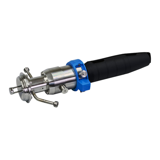
- Page 1 Products Solutions Services BA01279C/07/EN/01.13 71237906 Operating Instructions Cleanfit CPA875 Retractable process assembly for sterile and hygienic applications...
- Page 2 Possible consequences if ignored ‣ Preventive measures This symbol alerts you to situations which may result in NOTICE damage to property. Cause/situation Possible consequences if ignored ‣ Action/note Symbols additional information, tip permitted or recommended forbidden or not recommended Endress+Hauser...
-
Page 3: Table Of Contents
Cleanfit CPA875 Table of contents Basic safety instructions ... . . 4 Personnel requirements ..... . 4 Designated use . -
Page 4: Basic Safety Instructions
Designated use The Cleanfit CPA875 retractable assembly, which can be manually or pneumatically operated, is designed for the installation of sensors in tanks and pipelines. Its mechanical construction means that it can be operated in pressurized systems (see Technical data). -
Page 5: Incoming Acceptance And Product
Cleanfit CPA875 Incoming acceptance and product identification Incoming acceptance and product identification Incoming acceptance • Verify that the packaging is not damaged. • Notify your supplier of any damage to the packaging. Keep the damaged packaging until the matter has been settled. -
Page 6: Installation
Installation Cleanfit CPA875 Installation Installation 3.1.1 Orientation The assembly is designed for installation on vessels and pipes. Suitable process connections must be available for this. The assembly is designed in such a way that there are no restrictions with regard to its orientation. - Page 7 Cleanfit CPA875 Installation Process connection Height XP in mm (inch) CC Clamp ISO 2852, ASME BPE-2012, 2½" 13.0 (0.51) DA Aseptic DN 25, clampable, DIN 11864-3 A 16.0 (0.63) DC Aseptic DN 50 screw-in DIN 11864-1 A 16.0 (0.63) DF Aseptic DN 50 grooved flange DIN 11864-2 A 14.2 (0.56)
- Page 8 Installation Cleanfit CPA875 a0018666 Fig. 2: Dimensions for long version (78 mm stroke) Pneumatic drive Manual drive Manual drive with small protection cap Assembly in measuring position Assembly in service position Height of particular process connection (see table) Necessary mounting distance for sensor replacement The mounting distance XA is 440 mm (17.32") for 225 mm sensors...
- Page 9 Cleanfit CPA875 Installation 3.1.3 Immersion depths a0017745 Fig. 3: Immersion depths for different service chambers Single chamber / 36 mm stroke / sensor 225 mm incl. KCl Single chamber / 78 mm stroke / sensor 225 mm excl. KCl Single chamber / 78 mm stroke / sensor 360 mm incl. KCl Double chamber / 78 mm stroke / sensor 225 mm incl.
- Page 10 Installation Cleanfit CPA875 a0022162 Fig. 4: Immersion depth in mm (inch) for process connection NA thread ISO228 G1¼ (service chamber 2 and 3) Measuring position Service position Endress+Hauser...
-
Page 11: Installation
Cleanfit CPA875 Installation Installation 3.2.1 Measuring system with single chamber a0017811 Fig. 5: Measuring system (example) Cleanfit CPA875 assembly Measuring cable Liquiline CM44x transmitter Sensor 3.2.2 Measuring system with double chamber a0022821 Fig. 6: Measuring system with pneumatic drive and double chamber (example) - Page 12 Installation Cleanfit CPA875 3.2.3 Installing the assembly in the process WARNING If process medium leaks out, there is a risk of injury due to high pressure, high temperature or chemicals. ‣ Wear protective gloves, goggles and clothing. ‣ Install the assembly only if the tanks and piping are empty and unpressurized.
- Page 13 Cleanfit CPA875 Installation 3.2.4 Pneumatic connection for automatic operation Requirements: • Air pressure of 4 to 7 bar (58 to 102 psi) • Compressed air quality as per ISO 8573-1:2001 Quality class 3.3.3 or 3.4.3 (see below) • Solids class 3 (max. 5 μm, max. 5 mg/m •...
- Page 14 Installation Cleanfit CPA875 3.2.6 Assignment of rinse connections for double chamber a0023348 Fig. 9: Changing the chamber volume "Moving" seals in the double chamber Chamber volume in service position Chamber volume in measuring position a0022805 Fig. 10: Assignment of rinse inlet and outlet "Cleaning"...
- Page 15 Cleanfit CPA875 Installation In the "Move from measuring position to service position" state (C), the pressure conditions in the service chamber must be balanced when moving. The inlet and outlet of the service chamber are assigned as follows: • The air is supplied via the inlet (1).
-
Page 16: Installing The Sensor
Installation Cleanfit CPA875 Installing the sensor WARNING If process medium leaks out, there is a risk of injury due to high pressure, high temperature or chemicals. ‣ Wear protective gloves, goggles and clothing. ‣ Install the assembly only if the tanks and piping are empty and unpressurized. - Page 17 Cleanfit CPA875 Installation Installing and removing sensors if the sensor adapter is visible (pos. A) a0023186 Fig. 15: Sensor installation Open-ended wrench (AF 17/19 mm) Protective cap Dummy plug Sensor Gel and KCl sensors can be installed in this version.
- Page 18 Installation Cleanfit CPA875 Installing and removing sensors if the sensor adapter is not visible (pos. B) a0023256 Fig. 16: Sensor installation Open-ended wrench (AF 17/19 mm) Protective cap Dummy plug Sensor Retraction pipe Gel sensors can be installed in this version. To install KCl sensors, you will need a "Gel - KCl adapter".
- Page 19 Cleanfit CPA875 Installation Installation of 360 mm gel and KCL sensors with "Gel - KCl adapter" a0023304 Fig. 17: Sensor installation, Part 1 Open-ended wrench (AF 17/19 mm) Protective cap Dummy plug Retraction pipe Adapter gel - KCl Lock nut Install the sensor as follows: Remove the protective cap (...
-
Page 20: Post-Installation Check
Installation Cleanfit CPA875 a0023305 Fig. 18: Sensor installation, Part 2 Open-ended wrench Protective cap 360 mm gel or KCl sensor Always install the protective cap before moving the assembly to the measuring position. The protective cap cannot be removed in the measuring position. This prevents the sensor from being removed. -
Page 21: Operating Options
Cleanfit CPA875 Operating options Operating options Initial commissioning Prior to initial commissioning, ensure that: • all seals are correctly seated (on the assembly and on the process connection) • the sensor is correctly installed and connected • the water connection at the rinse connections is correct (if present). -
Page 22: Operating Elements
Operating options Cleanfit CPA875 Operating elements a0023307 Fig. 19: Position markings (service position) Assembly with pneumatic drive The assembly with pneumatic drive does not have any operating elements. Assembly with manual drive Manual drive Unlocking button a0023234 Fig. 20: Operating elements... -
Page 23: Manual Operation
Cleanfit CPA875 Operating options Manual operation a0023306 Fig. 21: Direction of rotation Moving the assembly from the service position to the measuring position Rotate the drive in a clockwise direction ( å 21), so that the sensor holder enters the process (this is possible only if a sensor is installed). -
Page 24: Pneumatic Operation
Operating options Cleanfit CPA875 Pneumatic operation The assembly can be moved only if a sensor is installed. The operation of the pneumatic version depends on the controller in question. The operating instructions can be found in the manual for the controller. -
Page 25: Maintenance
Cleanfit CPA875 Maintenance Maintenance WARNING Risk of injury if medium escapes ‣ Before each maintenance activity, verify that the process piping, the tank and the service chamber are unpressurized, empty and have been rinsed. ‣ Move the assembly to the "service" position. -
Page 26: Cleaning Agent
Maintenance Cleanfit CPA875 Cleaning agent The choice of cleaning agent depends on the degree and type of contamination. The most common types of contamination and the appropriate cleaning agents can be found in the following table. Type of contamination Cleaning agent... -
Page 27: Replacing Seals
Cleanfit CPA875 Maintenance Replacing seals To replace the seals in the assembly, you must interrupt the process and remove the assembly completely. CAUTION Risk of injury due to residual medium and elevated temperatures ‣ When handling parts which are in contact with the medium, protect yourself from residual medium and elevated temperatures. - Page 28 Maintenance Cleanfit CPA875 5.4.1 Molded seal - process connection (A) 1. Release the four securing screws ( å 23, pos. 1). a0022115 Fig. 23: Replacing seals, Part 1 Securing screws 2. Remove the process connection (pos. 2). 3. Remove the molded seal (pos. 5) from the process connection 4.
- Page 29 Cleanfit CPA875 Maintenance 5.4.2 O-rings - single chamber (B) 1. Release the four securing screws ( å 25, pos. 1). 2. Remove the service chamber (pos. 3) together with the process connection (pos. 2). a0022112 Fig. 25: Replacing seals, Part 1 Securing screws 3.
- Page 30 Maintenance Cleanfit CPA875 5.4.3 Molded seal - process connection, double chamber (C) 1. Release the four securing screws ( å 27, pos. 1). a0022299 Fig. 27: Replacing seals, Part 1 Securing screws 2. Remove the process connection (pos. 2). 3. Remove the molded seal (pos. 4) from the process connection 4.
- Page 31 Cleanfit CPA875 Maintenance 5.4.4 Molded seal - front chamber (D) 1. Release the four securing screws ( å 29, pos. 1). a0022301 Fig. 29: Replacing seals, Part 1 Securing screws 2. Remove the front chamber together with the process connection (pos. 2).
- Page 32 Maintenance Cleanfit CPA875 5.4.5 Seals - inner double chamber (E) 1. Release the four securing screws ( å 31, pos. 1). 2. Remove the service chamber with front chamber and process connection (pos. 2). a0022581 Fig. 31: Replacing seals, Part 1...
- Page 33 Cleanfit CPA875 Maintenance 5. Remove the molded seal ( å 33, pos. 5) using a tweezers or long-nose pliers. 6. Apply a thin layer of grease to the new molded seal (e.g. Klüber Paraliq GTE 703). 7. Press the molded seal into the guide groove of the immersion tube.
-
Page 34: Repair
The product must be returned if it is in need of repair or a factory calibration, or if the wrong product was ordered or delivered. Legal specifications require Endress+Hauser, as an ISO- certified company, to follow certain procedures when handling all returned products that have been in contact with the medium. -
Page 35: Accessories
Cleanfit CPA875 Accessories Accessories The most important accessories available at the time this document went to print are listed below. Please contact your sales center for accessories that are not listed here. The following accessories can be ordered via the product structure (see ordering information): •... -
Page 36: Installation Material For Rinse Connections
Accessories Cleanfit CPA875 Installation material for rinse connections Filter set CPC310, CVC400 • Water filter (dirt trap) 100 μm, complete, incl. angle bracket • Order No. 71031661 Pressure reducer kit • Complete, incl. manometer and angle bracket • Order No. 51505755 Hose connection nipples for rinse connections G ¼, DN 12... -
Page 37: Sensors
Cleanfit CPA875 Accessories Sensors 7.2.1 Glass electrodes Orbisint CPS11/CPS11D • pH electrode for process engineering • Optional SIL version for connection to SIL transmitter • With dirt-repellent PTFE diaphragm • Order as per product structure (--> Online Configurator, www.products.endress.com/ cps11 or www.products.endress.com/cps11d) •... - Page 38 Accessories Cleanfit CPA875 Orbipore CPS92/CPS92D • ORP electrode with open aperture diaphragm for media with high dirt load, • Order as per product structure (--> Online Configurator, www.products.endress.com/ cps92 or www.products.endress.com/cps92d) • Technical Information TI00435C/07/EN Memosens CPS96D • pH-ORP combination sensor for chemical processes •...
- Page 39 Cleanfit CPA875 Accessories 7.2.2 ISFET sensors Tophit CPS471/CPS471D • Sterilizable and autoclavable ISFET sensor for food and pharmaceutical industry, process engineering, • Water treatment and biotechnology; • Order as per product structure (--> Online Configurator, www.products.endress.com/ cps471 or www.products.endress.com/cps471d) • Technical Information TI00283C/07/EN Tophit CPS441/CPS441D •...
-
Page 40: Technical Data
Technical data Cleanfit CPA875 Technical data Environment Ambient temperature -10 to +70 °C (+ 14 to 158 °F) Storage temperature -10 to +70 °C (+ 14 to 158 °F) Process Process temperature -10 to +140 °C (14 to 284 °F) -
Page 41: Mechanical Construction
Cleanfit CPA875 Technical data Mechanical construction Design, dimensions see "Mounting" section Weight Depends on version: Pneumatic drive: 3.8 to 6 kg (8.4 to 13.2 lbs) Manual drive: 3 to 4.5 kg (6.6 to 9.9 lbs) Materials In contact with medium:... -
Page 42: Index
Cleanfit CPA875 Index Accessories ........35 Operating elements. - Page 43 Cleanfit CPA875 Endress+Hauser...
- Page 44 71237906 www.addresses.endress.com...
Need help?
Do you have a question about the Cleanfit CPA875 and is the answer not in the manual?
Questions and answers