Table of Contents
Advertisement
Quick Links
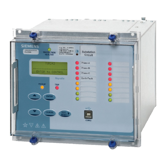
7SR242 Duobias
Multi-Function 2-Winding Transformer Protection Relay
Document Release History
This document is issue 2010/02. The list of revisions up to and including this issue is:
2010/06
Defect Report Form revised
2010/02
Document reformat due to rebrand
2010/02
Third issue. Software revision 2662H80001 R4c-3
2008/07
Second issue. Software revision 2662H80001R3d-2c.
2008/05
First issue
Software Revision History
2010/02
2662H80001 R4c-3
2008/07
2662H80001R3d-2c.
2008/05
2662H80001R3-2b
The copyright and other intellectual property rights in this document, and in any model or article produced from it
(and including any registered or unregistered design rights) are the property of Siemens Protection Devices
Limited. No part of this document shall be reproduced or modified or stored in another form, in any data retrieval
system, without the permission of Siemens Protection Devices Limited, nor shall any model or article be
reproduced from this document unless Siemens Protection Devices Limited consent.
While the information and guidance given in this document is believed to be correct, no liability shall be accepted
for any loss or damage caused by any error or omission, whether such error or omission is the result of
negligence or any other cause. Any and all such liability is disclaimed.
©2010 Siemens Protection Devices Limited
7SR242 Duobias Commissioning & Maintenance Guide
Revisions to: VT ratio settings, 87BD 1
increments, CB fail function, LED CONFIG menu, DATA STORAGE
menu.
Added: Open circuit detection (46BC), CONTROL MODE menu,
Close circuit supervision (74CCS), Measured earth fault undercurrent
(37G), Pulsed output contacts.
Demand metering. Optional DNP3.0 data comms.
First Release
st
bias slope limit setting
Advertisement
Table of Contents

Related Manuals for Siemens 7SR242 Duobias


Summary of Contents for Siemens 7SR242 Duobias
-
Page 1: Document Release History
Limited. No part of this document shall be reproduced or modified or stored in another form, in any data retrieval system, without the permission of Siemens Protection Devices Limited, nor shall any model or article be reproduced from this document unless Siemens Protection Devices Limited consent. -
Page 2: Table Of Contents
7SR242 Duobias Commissioning & Maintenance Guide Contents Document Release History........................1 Software Revision History........................1 Contents ..............................2 Section 1: Common Functions ......................5 1.1 Overview ...........................5 1.2 Before Testing...........................5 1.2.1 Safety ...........................5 1.2.2 Sequence of Tests .......................5 1.2.3 Test Equipment ......................6 1.2.4 Precautions ........................6 1.2.5... - Page 3 7SR242 Duobias Commissioning & Maintenance Guide 2.11 Under/Over Frequency (81) ....................43 2.12 Overfluxing (24) ........................45 2.12.1 definite time (24DT)....................45 2.12.2 inverse time (24IT) .....................46 Section 3: Supervision Functions ......................47 3.1 CB Fail (50BF) ........................47 3.2 Trip/Close Circuit Supervision (74TCS, 74CCS) ..............49 3.3 Magnetising Inrush Detector (81HBL2) ................50...
- Page 4 7SR242 Duobias Commissioning & Maintenance Guide List of Figures Figure 2-1 Biased Differential ......................14 Figure 2-2 Secondary Injection using a Variac ................15 Figure 2-3 Phase Overcurrent......................18 Figure 2-4 Measured Earth Fault......................21 Figure 2-5 Measured Earth Fault......................24 Figure 2-6 Restricted Earth Fault.......................27 Figure 2-7 Open Circuit........................29...
-
Page 5: Section 1: Common Functions
7SR242 Duobias Commissioning & Maintenance Guide Section 1: Common Functions Overview Commissioning tests are carried out to prove: Equipment has not been damaged in transit. Equipment has been correctly connected and installed. Prove characteristics of the protection and settings which are based on calculations. -
Page 6: Test Equipment
7SR242 Duobias Commissioning & Maintenance Guide 1.2.3 Test Equipment Required test equipment is: Secondary injection equipment with integral time interval meter Primary injection equipment A d.c. supply with nominal voltage within the working range of the relay's d.c. auxiliary supply rating A d.c. -
Page 7: Applying Settings
7SR242 Duobias Commissioning & Maintenance Guide 1.2.5 Applying Settings The relay settings for the particular application should be applied before any secondary testing occurs. If they are not available then the relay has default settings that can be used for pre-commissioning tests. See the Relay Settings section of this manual for the default settings. -
Page 8: Tests
7SR242 Duobias Commissioning & Maintenance Guide Tests 1.3.1 Inspection Ensure that all connections are tight and correct to the relay wiring diagram and the scheme diagram. Record any deviations. Check that the relay is correctly programmed and that it is fully inserted into the case. Refer to ‘Section 2: Settings and Instruments’... -
Page 9: Ac Energising Quantities
7SR242 Duobias Commissioning & Maintenance Guide AC Energising Quantities Voltage and current measurement for each input channel is displayed in the Instrumentation Mode sub-menus, each input should be checked for correct connection and measurement accuracy by single phase secondary injection at nominal levels. Ensure that the correct instrument displays the applied signal within limits of the Performance Specification. -
Page 10: Binary Inputs
7SR242 Duobias Commissioning & Maintenance Guide Binary Inputs The operation of the binary input(s) can be monitored on the ‘Binary Input Meters’ display shown in ‘Instruments Mode’. Apply the required supply voltage onto each binary input in turn and check for correct operation. -
Page 11: Binary Outputs
7SR242 Duobias Commissioning & Maintenance Guide Binary Outputs A minimum of six output relays are provided. Two of these have change over contacts, BO2 & BO3, one has a normally closed contact, BO1 and the remainder have normally open contacts. -
Page 12: Section 2: Protection Functions
7SR242 Duobias Commissioning & Maintenance Guide Section 2: Protection Functions This section details the procedures for testing each protection function of the 7SR24 relay. These tests are carried out to verify the accuracy of the protection pick-ups and time delays at setting and to confirm correct operation of any associated input and output functionality. - Page 13 7SR242 Duobias Commissioning & Maintenance Guide It should be considered that where several overlapping elements are used simultaneously, the overall protection operate time may be dependent on the operation of different individual elements at the various levels of applied current or voltage. The resulting composite characteristic may be tested by enabling all of the relevant applicable elements or the element operations can be separated or disabled and tested individually.
-
Page 14: Biased Differential (87Bd, 87Hs)
7SR242 Duobias Commissioning & Maintenance Guide Biased Differential (87BD, 87HS) Figure 2-1 Biased Differential Voltage Inputs: None Current Inputs: W1-I ),W1-I ),W1-I ), and W2-I ),W2-I ),W2-I Disable: 46, 49, 50, 51, 50N, 51N, 50BF, Map Pickup LED: 87BD, 87HS - Self Reset The differential elements are subjected to CT multipliers, Vector Group Compensation and Zero Sequence filters when applied to power transformers. -
Page 15: Figure 2-2 Secondary Injection Using A Variac
7SR242 Duobias Commissioning & Maintenance Guide Secondary testing of the bias characteristic will be greatly simplified by the use of automated numeric protection test equipment such as the Omicron CMC256. This equipment can be programmed using setting which match those of the relay to test for accuracy over the whole operating range and give a clear easy to use graphical display of relay performance against the specified characteristic. - Page 16 7SR242 Duobias Commissioning & Maintenance Guide 2.1.1.2 Results for testing 87BD with 2 current sources 87BD I 87BD 1 W1 C NITIAL URRENT ETTING LOPE ETTING 0.00 1.00 1.50 2.00 2.50 W2 Current (x I 0.10 0.10 1.11 1.66 2.21 2.76...
-
Page 17: Primary Injection Testing
7SR242 Duobias Commissioning & Maintenance Guide 2.1.2 Primary Injection Testing Primary injection is recommended to prove the relay connections, CT polarity and settings before putting the protection scheme into service. Primary injection is essential to fully prove the connections of the Biased Differential and REF protections. -
Page 18: Phase Overcurrent (50, 51)
7SR242 Duobias Commissioning & Maintenance Guide 2.1.3 Phase Overcurrent (50, 51) Figure 2-3 Phase Overcurrent Voltage Inputs: None Current Inputs: W1-I ), W1-I ), W1-I ), or W2-I ), W2-I ), W2-I Disable: 46, 49, 50BF, 87BD, 87HS Map Pickup LED:... -
Page 19: Definite Time Overcurrent (50)
7SR242 Duobias Commissioning & Maintenance Guide 2.1.4 Definite Time Overcurrent (50) If DTL setting is small, gradually increase current until element operates. If DTL is large apply 0.9x setting, check for no operation, apply 1.1x setting, check operation Apply 2x setting current if possible and record operating time Phas Dir. - Page 20 7SR242 Duobias Commissioning & Maintenance Guide 2.1.5.1 Element Blocking The Phase Overcurrent elements can be blocked by Binary Input Inhibit and Inrush Detector operation. This functionality should be checked. Element BI Inhibits Inrush Detector 51-1 51-2 50-1 50-2 2.1.5.2 ANSI Reset If the element is configured as an ANSI characteristic, it may have an ANSI (decaying) reset delay applied.
-
Page 21: Derived Earth Fault (50N,51N)
7SR242 Duobias Commissioning & Maintenance Guide Derived Earth fault (50N,51N) Figure 2-4 Measured Earth Fault Voltage Inputs: None Current Inputs: W1-I ), W1-I ), W1-I ), or W2-I ), W2-I ), W2-I Disable: 50BF, 50, 51, 49, 37 Map Pickup LED:... -
Page 22: Definite Time Overcurrent (50N)
7SR242 Duobias Commissioning & Maintenance Guide 2.2.1 Definite Time Overcurrent (50N) If DTL setting is small, gradually increase current until element operates. If DTL is large apply 0.9x setting, check for no operation, apply 1.1x setting, check operation Apply 2x setting current if possible and record operating time Input P.U. -
Page 23: Ansi Reset
7SR242 Duobias Commissioning & Maintenance Guide 2.2.2.1 Element Blocking The Measured Earth Fault elements can be blocked by Binary Input Inhibit, VT Supervision and Inrush Detector operation. The Characteristic can be made non-directional by VT Supervision. This functionality should be checked. -
Page 24: Measured Earth Fault (50G, 51G)
7SR242 Duobias Commissioning & Maintenance Guide Measured Earth fault (50G, 51G) Figure 2-5 Measured Earth Fault Voltage Inputs: None Current Inputs: G1 , Disable: 50BF, 64H Map Pickup LED: 51G-n/50G-n - Self Reset Other protection functions may overlap with these functions during testing, it may be useful to disable some functions to avoid ambiguity. -
Page 25: Definite Time Overcurrent (50G)
7SR242 Duobias Commissioning & Maintenance Guide 2.3.1 Definite Time Overcurrent (50G) If DTL setting is small, gradually increase current until element operates. If DTL is large apply 0.9x setting, check for no operation, apply 1.1x setting, check operation Apply 2x setting current if possible and record operating time Input P.U. -
Page 26: Ansi Reset
7SR242 Duobias Commissioning & Maintenance Guide 2.3.2.1 Element Blocking The Measured Earth Fault elements can be blocked by Binary Input Inhibit, VT Supervision and Inrush Detector operation. The Characteristic can be made non-directional by VT Supervision. This functionality should be checked. -
Page 27: Restricted Earth Fault (64H)
7SR242 Duobias Commissioning & Maintenance Guide Restricted Earth fault (64H) Figure 2-6 Restricted Earth Fault Voltage Inputs: Current Inputs: G1 , Disable: 50G, 51G, 50BF Map Pickup LED: 64H-n - Self Reset The external stabilising resistor value should be measured and compared to that specified in the settings data. - Page 28 7SR242 Duobias Commissioning & Maintenance Guide These elements can be enabled for the I or I current inputs by relay settings, ensure that current is injected on the correct input. Since the DTL setting is generally small the pick-up setting can be tested by gradually increasing current until element operates.
-
Page 29: Open Circuit (46Bc)
7SR242 Duobias Commissioning & Maintenance Guide Open Circuit (46BC) Figure 2-7 Open Circuit Voltage Inputs: Current Inputs: W1-I ), W1-I ), W1-I ), or W2-I ), W2-I ), W2-I Disable: 51N, 46IT, 46DT Map Pickup LED: 46BC - Self Reset This function uses the ratio of NPS current to PPS current to detect an open circuit . - Page 30 7SR242 Duobias Commissioning & Maintenance Guide 46BC Setting 1P unbalance current (% of 3P current) 100% 129% 161% 200% 46BC Setting 3P balanced current (A) 1P unbalance current (A) Measured Unbalance current 46BC-1 46BC-2 Apply 1A 1P unbalance current without 3P balanced current. Measure 46BC operating time.
-
Page 31: Negative Phase Sequence Overcurrent (46Nps)
7SR242 Duobias Commissioning & Maintenance Guide Negative Phase Sequence Overcurrent (46NPS) Figure 2-8 Negative Phase Sequence Overcurrent Voltage Inputs: Current Inputs: W1-I ), W1-I ), W1-I ), or W2-I ), W2-I ), W2-I Disable: 50, 51, 50BF, 87BD Map Pickup LED:... -
Page 32: Definite Time Nps Overcurrent (46Dt)
7SR242 Duobias Commissioning & Maintenance Guide 2.6.1 Definite Time NPS Overcurrent (46DT) If DTL setting is small, gradually increase current until element operates. If DTL is large apply 0.9x setting, check for no operation, apply 1.1x setting, check operation Apply 2x setting current if possible and record operating time... - Page 33 7SR242 Duobias Commissioning & Maintenance Guide 2.6.2.1 ANSI Reset If the element is configured as an ANSI characteristic, it may have a reset delay applied. If ANSI reset is selected for an IEC characteristic element, the reset will be instantaneous.
-
Page 34: Undercurrent (37, 37G)
7SR242 Duobias Commissioning & Maintenance Guide Undercurrent (37, 37G) Figure 2-9 Undercurrent Voltage Inputs: Current Inputs: W1-I ), W1-I ), W1-I ), I or W2-I ), W2-I ), W2-I ), I Disable: 50N, 51N, 51G, 46, 87BD Map Pickup LED: 37-n, 37G-n - Self Reset 2.7.1... -
Page 35: Elements
7SR242 Duobias Commissioning & Maintenance Guide Apply 0.5x setting current and record operating time Phase P.U. Current Operate Time NOTES (Amps) (sec) Amps 0.5 x Is Wn-I Wn-I Wn-I Wn-I Wn-I Wn-I Elements can be blocked by operation of a Binary Input Inhibit or by operation of the 37-n U/I Guard element. -
Page 36: Thermal Overload (49)
7SR242 Duobias Commissioning & Maintenance Guide Thermal Overload (49) Figure 2-10 Thermal Overload Voltage Inputs: Current Inputs: W1-I ), W1-I ), W1-I ), or W2-I ), W2-I ), W2-I Disable: 51, 50, 37, 46NPS, 50CBF, 87BD Map Pickup LED: 49 Alarm The current can be applied from a 3P balanced supply or phase by phase from a 1P supply. - Page 37 7SR242 Duobias Commissioning & Maintenance Guide Time Constant (mins) Operate Time (sec) 17.3 34.5 51.8 86.3 51.8 1726 The Thermal State must be in the fully reset condition in order to measure the operate time correctly. This can be achieved by setting change in the Thermal protection settings menu or by pressing the Test/Reset button when the Thermal Meter is shown in the Instruments Mode.
-
Page 38: Under/Over Voltage (27/59)
7SR242 Duobias Commissioning & Maintenance Guide Under/Over Voltage (27/59) Figure 2-11 Phase Under/Over Voltage Voltage Inputs: Current Inputs: n/a apply zero current to stabilize other functions Disable: Map Pickup LED: 27/59-n - Self Reset Where more than one Undervoltage (27) elements are being used with different settings, it is convenient to test the elements with the lowest settings first. - Page 39 7SR242 Duobias Commissioning & Maintenance Guide When testing is complete reinstate any of the disabled functions. Where more than one Overvoltage (59) elements are being used with different settings, it is convenient to test the elements with the highest settings first. The elements with lower settings can then be tested without disabling the higher settings.
-
Page 40: Undervoltage Guard (27/59Uvg)
7SR242 Duobias Commissioning & Maintenance Guide 2.9.2 Undervoltage Guard (27/59UVG) If any 27 Undervoltage element is set to be inhibited by the 27 Undervoltage Guard element, this function should be tested. Connect the test voltage inputs to suit the installation wiring diagram utilising any test socket facilities available. It may be useful to temporarily map an LED as ‘General Pickup’... -
Page 41: Neutral Over Voltage (59N)
7SR242 Duobias Commissioning & Maintenance Guide 2.10 Neutral Over Voltage (59N) Figure 2-12 Neutral Overvoltage Voltage Inputs: Current Inputs: n/a apply zero current to stabilize other functions Disable: 27/59 Map Pickup LED: 59N-n - Self Reset ©2010 Siemens Protection Devices Limited... -
Page 42: Definite Time (59Ndt)
7SR242 Duobias Commissioning & Maintenance Guide 2.10.1 Definite Time (59NDT) If DTL setting is small, gradually increase single phase voltage until element operates. If DTL is large apply 0.9x setting, check for no operation, apply 1.1x setting, check operation Apply 2x setting voltage if possible and record operating time Phase P.U. -
Page 43: Under/Over Frequency (81)
7SR242 Duobias Commissioning & Maintenance Guide 2.11 Under/Over Frequency (81) Figure 2-13 Under/Over Frequency Voltage Inputs: Current Inputs: n/a apply zero current to stabilize other functions Disable: Map Pickup LED: 81-n - Self Reset For Over-frequency, the elements with the highest setting should be tested first and for Under-frequency the elements with the lowest settings should be tested first. - Page 44 7SR242 Duobias Commissioning & Maintenance Guide The frequency should then be gradually decreased/increased until the element resets. The reset frequency can be used to check the Hysteresis setting. If the element is set as 81-n U/V Guarded, The applied voltage must be above the 81 UV Guard Setting in the U/O Frequency menu.
-
Page 45: Overfluxing (24)
7SR242 Duobias Commissioning & Maintenance Guide 2.12 Overfluxing (24) Figure 2-14 Under/Over Frequency The settings are set in terms of V/f based on multiple of nominal voltage and frequency. Application of a voltage of nominal voltage and frequency represents 1.0. -
Page 46: Inverse Time (24It)
7SR242 Duobias Commissioning & Maintenance Guide 2.12.2 inverse time (24IT) The inverse V/f element should be tested at each of the points specified by settings that constitute the overall inverse characteristics. Setting Setting Hysteresis Calculated P.U. D.O. Operate NOTES (xVn) (volts) D.O. -
Page 47: Section 3: Supervision Functions
7SR242 Duobias Commissioning & Maintenance Guide Section 3: Supervision Functions CB Fail (50BF) Figure 3-1 CB Fail Voltage Inputs: Current Inputs: W1-I ), W1-I ), W1-I ), I or W2-I ), W2-I ), W2-I ), I Disable: Map Pickup LED:... - Page 48 7SR242 Duobias Commissioning & Maintenance Guide These elements are operated from W1 and W2 current inputs, ensure that current is injected on the correct input for the element being tested. Apply a trip condition by injection of current to cause operation of a suitable protection element. Allow current to continue after the trip at a level of 110% of the 50BF Setting current level on any phase.
-
Page 49: Trip/Close Circuit Supervision (74Tcs, 74Ccs)
7SR242 Duobias Commissioning & Maintenance Guide Trip/Close Circuit Supervision (74TCS, 74CCS) Figure 3-2 Trip Circuit Supervision Voltage Inputs: Current Inputs: Disable: Map Pickup LED: 74TCS-n/74CCS-n - Self Reset The T/CCS-n Delay can be initiated by applying an inversion to the relevant status input and measured by monitoring of the alarm output. -
Page 50: Magnetising Inrush Detector (81Hbl2)
7SR242 Duobias Commissioning & Maintenance Guide Magnetising Inrush Detector (81HBL2) Figure 3-3 Magnetising Inrush Detector Voltage Inputs: Current Inputs: W1-I ), W1-I ), W1-I ), or W2-I ), W2-I ), W2-I Disable: Map Pickup LED: Logical operation of the harmonic blocking can be tested by injection of 2 harmonic current (at 100Hz for 50Hz relay) to cause operation of the blocking signals. - Page 51 7SR242 Duobias Commissioning & Maintenance Guide A compromise test can be made by the use of a diode to generate a half-wave rectified waveform from a sinusoidal source. The half-wave rectified current will contain a combination of fundamental and harmonic currents.
-
Page 52: Overfluxing Detector (81Hbl5)
7SR242 Duobias Commissioning & Maintenance Guide Overfluxing Detector (81HBL5) Figure 3-4 Magnetising Inrush Detector Voltage Inputs: Current Inputs: W1-I ), W1-I ), W1-I ), or W2-I ), W2-I ), W2-I Disable: Map Pickup LED: Logical operation of the harmonic blocking can be tested by injection of 5 harmonic current (at 250Hz for 50Hz relay) to cause operation of the blocking signals. -
Page 53: Section 4: Control & Logic Functions
7SR242 Duobias Commissioning & Maintenance Guide Section 4: Control & Logic Functions Quick Logic If this functionality is used, the logic equations may interfere with testing of other protection functions in the relay. The function of the Quick Logic equations should be tested conjunctively with connected plant or by simulation to assess suitability and check for correct operation on an individual basis with tests specifically devised to suit the particular application. -
Page 54: Section 5: Testing And Maintenance
It may however be convenient to fit the withdrawable relay to the outer case from a spare relay, to avoid the disturbance of relay panel wiring, for return to Siemens Protection Devices Ltd. The withdrawable relay should never be transported without the protection of the outer case. - Page 55 If the above checklist does not help in correcting the problem please contact the local Siemens office or contact PTD 24hr Customer Support, Tel: +49 180 5247000, Fax: +49 180 524 2471, e-mail: support.energy@siemens.com.
-
Page 56: Defect Report Form
7SR242 Duobias Commissioning & Maintenance Guide Defect Report Form Form sheet for repairs and returned goods (fields marked with * are mandatory fields) Sender: Complete phone number (incl. country code): Complete fax number (incl. country code): * Name, first name:... - Page 57 7SR242 Duobias Commissioning & Maintenance Guide Siemens Protection Devices Ltd. PO Box 8 Hebburn Tyne & Wear NE31 1TZ England Telephone: (0191) 401 5555 Fax: (0191) 401 5575 ©2010 Siemens Protection Devices Limited Chapter 6 Page 57 of 57...
Need help?
Do you have a question about the 7SR242 Duobias and is the answer not in the manual?
Questions and answers