Table of Contents
Advertisement
JUNE 2001
LE2801A
LE2801AE
LE2801A-BNC
LE2801AE-BNC
LE2801A-FO
LE2801AE-FO
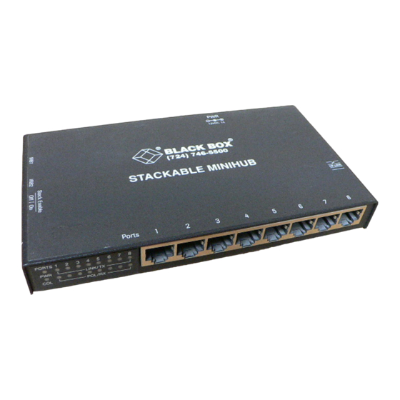
Stackable MiniHub
8
7
6
5
4
3
2
1
S
P O R T
T X
L I N K /
P W R
X
P O L / T
C O L
CUSTOMER
Order toll-free in the U.S. 24 hours, 7 A.M. Monday to midnight Friday: 877-877-BBOX
FREE technical support, 24 hours a day, 7 days a week: Call 724-746-5500 or fax 724-746-0746
SUPPORT
Mail order: Black Box Corporation, 1000 Park Drive, Lawrence, PA 15055-1018
INFORMATION
Web site: www.blackbox.com • E-mail: info@blackbox.com
Advertisement
Table of Contents

Related Manuals for Black Box Stackable MiniHub


Summary of Contents for Black Box Stackable MiniHub
- Page 1 Order toll-free in the U.S. 24 hours, 7 A.M. Monday to midnight Friday: 877-877-BBOX FREE technical support, 24 hours a day, 7 days a week: Call 724-746-5500 or fax 724-746-0746 SUPPORT Mail order: Black Box Corporation, 1000 Park Drive, Lawrence, PA 15055-1018 INFORMATION Web site: www.blackbox.com • E-mail: info@blackbox.com...
- Page 2 FCC AND IC STATEMENTS FEDERAL COMMUNICATIONS COMMISSION AND INDUSTRY CANADA RADIO FREQUENCY INTERFERENCE STATEMENT Class B Digital Device. This equipment has been tested and found to comply with the limits for a Class B computing device pursuant to Part 15 of the FCC Rules. These limits are designed to provide reasonable protection against harmful interference in a residential installation.
- Page 3 STACKABLE MINIHUB NORMAS OFICIALES MEXICANAS (NOM) ELECTRICAL SAFETY STATEMENT INSTRUCCIONES DE SEGURIDAD 1. Todas las instrucciones de seguridad y operación deberán ser leídas antes de que el aparato eléctrico sea operado. 2. Las instrucciones de seguridad y operación deberán ser guardadas para referencia futura.
- Page 4 NOM STATEMENT, TRADEMARKS 11. El aparato eléctrico deberá ser connectado a una fuente de poder sólo del tipo descrito en el instructivo de operación, o como se indique en el aparato. 12. Precaución debe ser tomada de tal manera que la tierra fisica y la polarización del equipo no sea eliminada.
-
Page 5: Table Of Contents
3.6 Fiberoptic Connection (LE2801A-FO, LE2801AE-FO only)....17 4. Operation ....................19 4.1 LED Indicators ..................19 4.2 Operating Features ................19 5. Troubleshooting ..................20 5.1 Things to Check .................. 20 5.2 Calling Black Box ................21 5.3 Shipping and Packaging ..............21... -
Page 6: Specifications
CHAPTER 1: Specifications 1. Specifications Compliance — FCC Part 15 Class A and B, IC Class/classe B, VDE Class B Standard — IEEE 802.3 Ethernet v. 1.0/2.0 Interface — LE2801A, LE2801AE: 10BASE-T; LE2801A-BNC, LE2801AE-BNC: 10BASE2; LE2801A-FO, LE2801AE-FO: 10BASE-FL 10 Mbps Data Rate —... - Page 7 STACKABLE MINIHUB Connectors — LE2801A, LE2801AE: (8) front-mounted shielded- type RJ-45 female; (1) rear-mounted DB15 female AUI port; LE2801A-BNC, LE2801AE-BNC: same as LE2801A, plus (1) rear-mounted BNC with internal termination switch; LE2801A-FO, LE2801AE-FO: same as LE2801A, plus one rear fiber ST connector Leads/Signals Supported —...
-
Page 8: Introduction
2. Introduction 2.1 General Overview The Stackable MiniHub is a workplace hub in a very compact package. It is simple to install and use in an office or lab environment, requiring no special rack cabinets or wiring-closet apparatus. It is a standard physical-layer Ethernet product and operates independently of all software. - Page 9 STACKABLE MINIHUB The Stackable MiniHub’s RJ-45 ports support connection of up to eight workstations or other network devices over full-length 10BASE-T cable segments. Stackable MiniHubs fully comply with the IEEE 802.3 specification for repeater functionality: They perform signal amplification, retiming of data packets, and regeneration of preamble bits for each packet received.
-
Page 10: Features And Benefits
2.2 Features and Benefits • Interconnectability with Existing Ethernet Networks Your Stackable MiniHub has a manual Up-Link switch that you can use to cross the pinning of its 8th port. In this setting, you can connect 10BASE- T cable from an existing Ethernet environment (such as the central hub for the building) to the MiniHub’s 8th port. - Page 11 • Low-Cost Standalone 10BASE-T Connectivity Operating your Stackable MiniHub in a standalone environment as a self- sufficient device is a very low-cost method of providing small workgroups access to a variety of Ethernet networking services such as file sharing, email, printer sharing, and other computer information.
-
Page 12: Applications
CHAPTER 2: Introduction 2.3 Applications Expanding from one to multiple ports at an existing site is easy, and requires no modification to typical building wiring. Simply plug the existing networked device’s network-cable segment into one of the Stackable MiniHub’s front-mounted RJ-45ports. With the MiniHub’s rear-mounted Up- Link switch set to “= =”, run 10BASE-T cable from the existing network outlet to the MiniHub’s 8th port. - Page 13 In this application, set the Up-Link switch to the straight- through or “= = =” position, so that the MiniHub’s 8th port is a user port, not an up-link to another hub. Figure 2-4. Using the Stackable MiniHub as a Standalone Hub.
-
Page 14: Installation
Remove the Stackable MiniHub from the shipping container. Keep the container in case you need to ship the unit later. If any items are missing or damaged, contact Black Box. If you need to return the unit, see Sections 5.2 and 5.3. - Page 15 MiniHub with screws, as shown below. You can use the metal screws in each side of the Stackable MiniHub’s case to attach the brackets. With the brackets, you can mount the MiniHub in almost any desired position.
- Page 16 Even when the rear port is physically uplinked (cable runs from the port to a larger network), you can logically isolate the users and devices on the Stackable MiniHub by moving the Up-Link switch to the “= = =” position. In this situation, the uplink segment is inoperative and full bandwidth is...
-
Page 17: Stacking The Minihubs
STACKABLE MINIHUB 3.3 Stacking the MiniHubs When you need increased network capacity, you can easily stack up to five Stackable MiniHubs to form a single logical repeater of up to 40 RJ-45 ports. P O R T L I N K /... - Page 18 CHAPTER 3: Installation Follow these steps when stacking: 1. Switch the Stack Enable switch of the bottom Stackable MiniHub to the “OFF” position (left). 2. Switch all other units to the “ON” position (right). 3. Using the IRB ribbon cable, connect one end to either Inter-Repeater- Bus connector (IRB1 or IRB2) of the bottom Stackable MiniHub.
- Page 19 STACKABLE MINIHUB P O R T L I N K / P W R P O L / T C O L P O R T P O R T L I N K / L I N K /...
- Page 20 CHAPTER 3: Installation P O R T L I N K / P W R P O L / T C O L P O R T L I N K / P W R P O L / T C O L P O R T L I N K /...
-
Page 21: Cascading
10BASE-T cable from the MiniHub’s rear-panel port to any port of another 10BASE-T hub, as shown in the illustration below. Since each Stackable MiniHub provides full repeater functionality, cascaded units can operate together even though there may be a full segment of distance between them. -
Page 22: Bnc Connection (Le2801A-Bnc, Le2801Ae-Bnc Only)
BNC port is specially equipped with an internal termination switch that eliminates the need to use a “tee” connector when the BNC cable is ending at the Stackable MiniHub. When the switch is in the right position, the connection is internally terminated. When switched to the left position, external termination (“tee”... - Page 23 (and when power is ON in the unit). If LINK is not lit after cable connection, the normal cause is improper cable polarity. Swap the fiber cables at the Stackable MiniHub’s rear fiber port connectors to remedy this situation in most cases.
-
Page 24: Operation
CHAPTER 4: Operation 4. Operation 4.1 LED Indicators Power On (PWR) LED: Shines GREEN to show functional DC power. Link Status (LINK) LEDs: Stackable MiniHubs have a LINK LED for each port, which shines GREEN when the MiniHub detects that a 10BASE-T segment is properly connected to that port. -
Page 25: Troubleshooting
Black Box; see Section 5.2. 5.1 Things to Check 1. If you a problem installing or operating the Stackable MiniHub, refer back to Chapters 3 and 4. Check to make sure that the various other components of the network are operable. -
Page 26: Calling Black Box
5.2 Calling Black Box If you determine that your Stackable MiniHub is malfunctioning, do not attempt to alter or repair it. Contact Black Box at 724-746-5500. The problem might be solvable over the phone. Before you do, make a record of the history of the problem. We will be... - Page 27 © Copyright 2001. Black Box Corporation. All rights reserved. 1000 Park Drive • Lawrence, PA 15055-1018 • 724-746-5500 • Fax 724-746-0746...
Need help?
Do you have a question about the Stackable MiniHub and is the answer not in the manual?
Questions and answers