Table of Contents
Advertisement
Available languages
Available languages
Quick Links
Advertisement
Chapters
Table of Contents

Related Manuals for ProLights LEDPAR64363RGB


Summary of Contents for ProLights LEDPAR64363RGB
- Page 1 LEDPAR64363RGB LED LIGHTING EFFECT Manuale Utente User Manual...
- Page 2 REV.001-11/11...
-
Page 3: Table Of Contents
1. 1 Descrizione 1. 2 Specifiche tecniche 1. 3 Elementi di comando e collegamenti 2 Installazione 2. 1 Montaggio 3 Funzioni e impostazioni 3. 1 Funzionamento 3. 2 Impostazione base 3. 3 Struttura menu 3. 4 Modalità automatica 3. 5 Static color 3. 6 Modalità musicale 3. 7 Modalità Master/Slave 3. 8 Collegamento 3. 9 Modalità DMX 3. 10 Indirizzamento DMX 3. 11 Collegamenti della linea DMX 3. 12 Costruzione del terminatore DMX 3. 13 Tabella canali DMX 4 Manutenzione 4. 1 Manutenzione e pulizia del sistema ottico Certificato di garanzia CONTENUTO DELL'IMBALLO • LEDPAR64363RGB • Staffa di fissaggio (2pz.) • Manuale utente Music & Lights S.r.l. si riserva ogni diritto di elaborazione in qualsiasi forma delle presenti istruzioni per l’uso. La riproduzione - anche parziale - per propri scopi commerciali è vietata. Tutte le specifiche possono essere variate senza alcuna notifica. -
Page 4: Avvertenze Generali
LEDPAR64363RGB ATTENZIONE! Prima di effettuare qualsiasi operazione con l’unità, leggere con attenzione questo manuale e conservarlo accuratamente per riferimenti futuri. Contiene informazioni importanti riguardo l’installazione, l’uso e la manutenzione dell’unità. SICUREZZA Avvertenze generali • I prodotti a cui questo manuale si riferisce sono conformi alle Direttive della Comunità Europea e per- tanto recano la sigla . • Il dispositivo funziona con pericolosa tensione di rete 230V~. Non intervenire mai al suo interno al di fuori delle operazioni descritte nel presente manuale; esiste il pericolo di una scarica elettrica. -
Page 5: Informazioni Generali
LEDPAR64363RGB INFORMAZIONI GENERALI Spedizioni e reclami Le merci sono vendute “franco nostra sede” e viaggiano sempre a rischio e pericolo del distributore/clien- te. Eventuali avarie e danni dovranno essere contestati al vettore. Ogni reclamo per imballi manomessi dovrà essere inoltrato entro 8 giorni dal ricevimento della merce. Garanzie e resi Il prodotto è coperto da garanzia in base alle vigenti normative. Sul sito www.musiclights.it è possibile consultare il testo integrale delle “Condizioni Generali di Garanzia”. Si prega, dopo l’acquisto, di procedere alla registrazione del prodotto sul sito www.musiclights.it. In alternativa il prodotto può essere registrato compilando e inviando il modulo riportato alla fine del manuale. A tutti gli effetti la validità della garanzia è avallata unicamente dalla presentazione del certificato di garanzia. Music & Lights constata tramite ve- rifica sui resi la difettosità dichiarata, correlata all’appropriato utilizzo, e l’effettiva validità della garanzia; provvede quindi alla riparazione dei prodotti, declinando tuttavia ogni obbligo di risarcimento per danni diretti o indiretti eventualmente derivanti dalla difettosità. Le informazioni riportate in questo manuale sono state attentamente controllate. Music & Lights S.r.l. non si assume, tuttavia, responsabilità derivanti da eventuali inesattezze. -
Page 6: Introduzione
LEDPAR64363RGB - 1 - INTRODUZIONE 1.1 DESCRIZIONE Proiettore PAR64 a tecnologia LED con 36 LEDs RGB, 3W ciascuno. LEDPAR64363RGB è un proiettore ad alta efficienza luminosa e con un largo range cromatico grazie alla miscelazione colore RGB (>16 milioni di colori). LEDPAR64363 è stato concepito per sostituire i tradizionali proiettori PAR basati su funzionamento a lampada, permettendo di rimpiazzare numerosi set di PAR con gelatina colorata con un unico proiettore, riducendo i consumi a soli 120W e senza costi di manutenzione. 1.2 SPECIFICHE TECNICHE Sorgente luminosa e ottica • 36 x 3W LEDs RGB (12 rosso, 12 verde, 12 blu ) ad alta efficienza, con colori più vividi e minore assorbi- mento energetico delle lampade tradizionali • Sistema di sintesi colore: miscelazione RGB (>16 milioni di colori) per possibilità cromatiche illimitate • Gruppo ottico: lenti antiriflesso ad alta definizione, angolo di proiezione: 30° • Durata media diodi LED: >50.000 ore Funzionamento ed elettronica • Pannello di controllo tramite display LED (4-caratteri) • Diverse configurazioni DMX disponibili (3, 5 canali) per controllo professionale o semplificato • 3 canali: Auto programs, velocità di esecuzione, strobo • 5 canali: RGB, dimmer, strobo • Modalità Automatica: 7 programmi automatici preimpostati, regolazione di potenza, velocità di esecu- zione e controllo strobo • Modalità Colori statici: selezione statica di un colore... -
Page 7: Elementi Di Comando E Collegamenti
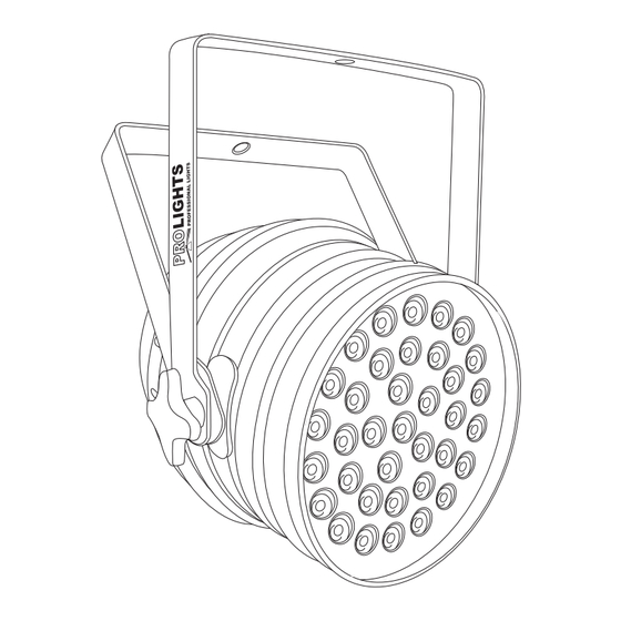
LEDPAR64363RGB 1.3 ELEMENTI DI COMANDO E COLLEGAMENTI MODE SETUP DOWN FUSE 1A/250V DMX IN DMX OUT Vista Posteriore Vista Laterale Fig.1 1. STAFFA DI MONTAGGIO 2. MANOPOLA DI FISSAGGIO per la staffa di montaggio. 3. COPERCHIO del proiettore 4. CAVO DI ALIMENTAZIONE 5. PANNELLO DI CONTROLLO con display e 4 pulsanti per accesso e gestione delle diverse funzioni 6. FUSIBILE 1A/250V 7. DMX IN (XLR 3 poli):... -
Page 8: Installazione
LEDPAR64363RGB - 2 - INSTALLAZIONE 2.1 MONTAGGIO LEDPAR64363RGB può essere collocato su un piano solido. Inoltre, grazie alle possibilità di fissaggio sulla doppia staffa (fig.2), l’unità può essere montata anche a testa in giù, su una traversa. Per il fissaggio oc- corrono dei supporti robusti per il montaggio. L’area di collocazione deve avere una stabilità sufficiente e supportare almeno 10 volte il peso dell’unità. Inoltre assicurarsi di rispettare tutte le avvertenze in materia di sicurezza. • Fissare il proiettore attraverso l’apposita staffa (1) ad una collocazione idonea. • È assolutamente necessario assicurare il proiettore contro la caduta utilizzando un cavo di sicurezza: in particolare collegare il cavo in un punto adatto in modo che la caduta del proiettore non possa supe- rare i 20 cm. • Orientare il proiettore intervenendo, se necessario, sulla manopola della staffa di montaggio (2). Fig.2... -
Page 9: Funzioni E Impostazioni
LEDPAR64363RGB - 3 - FUNZIONI E IMPOSTAZIONI 3.1 FUNZIONAMENTO Per accendere il LEDPAR64363RGB, inserire la spina del cavo di alimentazione in una presa di rete (240V~ 50Hz). L’unità può essere comandata da un unità DMX di comando luce oppure svolgere autonomamente il suo programma. Per spegnere il LEDPAR64363RGB, staccare la spina dalla presa di rete. Per maggiore comodità è consigliabile collegare l’unità con una presa comandata da un interruttore. 3.2 IMPOSTAZIONE BASE Il proiettore LEDPAR64363RGB dispone di un LED display e 4 pulsanti per accesso alle funzioni del pannel- lo di controllo (fig.3). MODE SETUP DOWN Fig.3 MODE SETUP DOWN Premendo questo tasto, Tasto per accedere alle Tasto per selezionare i valori Tasto per selezionare i valori è... -
Page 10: Struttura Menu
LEDPAR64363RGB 3.3 STRUTTURA MENU AUTO d.001 - d.512 d - P1 d.000 - d.512 d - P2 d.000 - d.512 MENU SLAv SU.00 - SU.31 SU.00 - SU.31 Pr.01 - Pr.11 Pr.01 1.--r r.000 - r.255 FS.00 - FS.99 2.-r9 r.000 - r.255... -
Page 11: Modalità Automatica
2-rG, 3-G, 4-Gb, 5-b, 6-rb e 7rGb. • Infine, premere nuovamente il tasto SETUP per impostare i valori desiderati della luminosità (000-255) e per l’effetto strobo [FS.00 - FS.99] attraverso i tasti UP e DOWN. 3.6 MODALITÀ MUSICALE Per entrare nella modalità musicale bisogna procedere come segue: • Premere il tasto MODE fino a quando sul display non appare [SU.(00-31)]. • Premere i tasti UP o DOWN per selezionare i differenti valori della sensibilità SU.(00-31). 3.7 MODALITÀ MASTER/SLAVE Questa modalità consente di collegare in linea più unità LEDPAR64363RGB senza un controller. La prima unità sarà impostata come master e le altre funzioneranno come slave con lo stesso effetto. • Premere il tasto MODE fino a quando sul display non appare [SLAv]. • Sull’unità master selezionare il programma desiderato come indicato al paragrafo 3.4. • Servirsi dei connettori DMX del LEDPAR64363RGB e di un cavo XLR per formare una catena di unità. In certe condizioni e lunghezze si consiglia di effettuare una terminazione come mostrato a pagina 13. 3.8 COLLEGAMENTO Si possono collegare più unità affinché tutte le unità secondarie abbiano lo stesso effetto luce dell’unità principale (Master). 1. Collegare l’uscita DMX OUT dell’unità principale con l’ingresso DMX IN della prima unità secondaria servendosi di un cavo XLR a 3 poli. 2. Collegare l’uscita DMX OUT della prima unità secondaria con l’ingresso DMX IN della seconda unità secondaria ecc. -
Page 12: Modalità Dmx
LEDPAR64363RGB 3.9 MODALITÀ DMX • Per poter entrare nella modalità DMX; premere il tasto MODE fino a quando sul display non appare [d.(001-512)]. • Premere il tasto SETUP per selezionare la configurazione dei canali DMX che si desidera (d-P1 - d-P2) attraverso i tasti UP e DOWN. • Premere il tasto SETUP per impostare il valore desiderato (001-512); tenere premuto il tasto UP o DOWN per lo scorrimento veloce. • Al termine dell’impostazione il valore verrà salvato automaticamente. Le tabelle a pagina 14 indicano le modalità di funzionamento e i relativi valori DMX. Come interfaccia DMX, l’unità possiede dei contatti XLR a 3 poli. -
Page 13: Collegamenti Della Linea Dmx
LEDPAR64363RGB 3.11 COLLEGAMENTI DELLA LINEA DMX La connessione DMX è realizzata con connettori standard XLR. Utilizzare cavi schermati, 2 poli ritorti, con impedenza 120Ω e bassa capacità. Per il collegamento fare riferimento allo schema di connessione riportato di seguito: DMX - INPUT DMX - OUTPUT Spina XLR Presa XLR Pin1 : Massa - Schermo Pin2 : - Negativo Pin3 : + Positivo Fig.5 ATTENZIONE La parte schermata del cavo (calza) non deve mai essere collegata alla terra dell’impianto; ciò comporte- rebbe malfunzionamenti delle unità e dei controller. Per passaggi lunghi può essere necessario l’inserimento di un amplificatore DMX. In tal caso, è sconsigliato utilizzare nei collegamenti cavo bilanciato microfonico poiché non è in grado di trasmettere in modo affidabile i dati di controllo DMX. • Collegare l’uscita DMX del controller con l’ingresso DMX della prima unità; • Collegare, quindi, l’uscita DMX con l’ingresso DMX della successiva unità; l’uscita di quest’ultima con l’ingresso di quella successiva e via dicendo finchè tutte le unità sono collegate formando una catena. • Per installazioni in cui il cavo di segnale deve percorrere lunghe distanze è consigliato inserire sull’ulti- ma unità una terminazione DMX. 3.12 COSTRUZIONE DEL TERMINATORE DMX La terminazione evita la probabilità che il segnale DMX 512, una volta raggiunta la fine della linea stessa... -
Page 14: Tabella Canali Dmx
LEDPAR64363RGB 3.13 TABELLA CANALI DMX Mode1 (5ch): d-P1 Function in the 5 channel mode DMX value RED 0 - 100% 000 - 255 (OFF when the CH5 is 001-005) GREEN 0 - 100% 000 - 255 (OFF when the CH5 is 001-005) -
Page 15: Manutenzione
LEDPAR64363RGB - 4 - MANUTENZIONE 4.1 MANUTENZIONE E PULIZIA DEL SISTEMA OTTICO • Durante gli interventi, assicurarsi che l’area sotto il luogo di installazione sia libera da personale non qualificato. • Spegnere l’unità, scollegare il cavo di alimentazione ed aspettare finché l’unità non si sia raffreddata. • Tutte le viti utilizzate per l’installazione dell’unità e le sue parti devono essere assicurate saldamente e • non devono essere corrose. • Alloggiamenti, elementi di fissaggio e di installazione (soffitto, truss, sospensioni) devono essere total- mente esenti da qualsiasi deformazione. • I cavi di alimentazione devono essere in condizione impeccabile e devono essere sostituiti immediata- mente nel momento in cui anche un piccolo problema viene rilevato. • Si dovrebbe procedere, ad intervalli regolari, alla pulizia della parte frontale per asportare polvere, fumo e altre particelle. Solo così, la luce può essere irradiata con la luminosità massima. Per la pulizia... -
Page 17: Ledpar64363Rgb
1 Introduction 1. 1 Description 1. 2 Technical specifications 1. 3 Operating elements and connection 2 Installation 2. 1 Mounting 3 Functions and settings 3. 1 Operation 3. 2 Basic 3. 3 Menu structure 3. 4 Automatic mode 3. 5 Static color 3. 6 Sound mode 3. 7 Master/Slave mode 3. 8 Linking 3. 9 DMX mode 3. 10 DMX addressing 3. 11 Connection of the DMX line 3. 12 Construction of the DMX termination 3. 13 DMX control 4 Maintenance 4. 1 Maintenance and cleaning the unit Warranty PACKING CONTENT • LEDPAR64363RGB • Mount bracket (2 pc.) • User manual All rights reserved by Music & Lights S.r.l. No part of this instruction manual may be. Reproduced in any form or by any means for any commercial use. Design and specifications are subject to change without notice. -
Page 18: General Instructions
LEDPAR64363RGB WARNING! Before carrying out any operations with the unit, carefully read this instruction manual and keep it with cure for future reference. It contains important information about the installation, usage and maintenance of the unit. SAFETY General instruction • The products referred to in this manual conform to the European Community Directives and are there- fore marked with . -
Page 19: General Information
LEDPAR64363RGB GENERAL INFORMATION Shipments and claims The goods are sold “ex works” and always travel at the risk and danger of the distributor. Eventual dam- age will have to be claimed to the freight forwarder. Any claim for broken packs will have to be forwarded within 8 days from the reception of the goods. Warranty and returns The guarantee covers the fixture in compliance with existing regulations. You can find the full version of the “General Guarantee Conditions” on our web site www.musiclights.it. Please remember to register the piece of equipment soon after you purchase it, logging on www.musiclights.it. The product can be also registered filling in and sending the form available on your guarantee certificate. For all purposes, the va- lidity of the guarantee is endorsed solely on presentation of the guarantee certificate. Music & Lights will verify the validity of the claim through examination of the defect in relation to proper use and the actual validity of the guarantee. Music & Lights will eventually provide replacement or repair of the products de- clining, however, any obligation of compensation for direct or indirect damage resulting from faultiness. The information provided in this manual has been carefully checked. However Music & Lights S.r.l. is not responsible for any possible inaccuracy. -
Page 20: Introduction
LEDPAR64363RGB - 1 - INTRODUCTION 1.1 DESCRIPTION PAR64 projector based on LED technology with 36 LEDs, 3W each. LEDPAR6436 has an impressive light emission with an unlimited chromatic range allowed by RGB colour mixing (>16 million colours). LEDPAR64363 has been conceived to substitute the old-fashioned Parcans projectors based on halogen lamps, allowing to replace the numerous Par-sets equipped with filter frame with only one fixture, reducing consumption to 120W, with no-need of additional costs for maintenance. 1.2 TECHNICAL SPECIFICATIONS Light source and optics • 36 x 3W RGB LEDs (12 red, 12 green, 12 blue), for more vivid colours and lower power consumption than traditional lamps • Colour synthesis: RGB color mixing (>16 million colours) for a limitless colour range • Projection angle: 30° • LEDs average life span: >50’000 hours Electronics and features • User interface: LED (4 char) display • Several DMX configurations selectable (3, 5 channels) for professional or simplified controlling • 3 channels: Auto programs, execution speed, strobe • 5 channels: RGB, dimmer, strobe • Auto mode: 7 built-in programs with brightness adjustments, execution speed, strobe activation • Static colour mode: selection of static colour... -
Page 21: Operating Elements And Connection
LEDPAR64363RGB 1.3 OPERATING ELEMENTS AND CONNECTIONS MODE SETUP DOWN FUSE 1A/250V DMX IN DMX OUT Rear panel Side view Fig.1 1. MOUNTING BRACKET 2. LOCKING KNOB for the mounting bracket. 3. PROJECTOR BACK COVER 4. CAVO DI ALIMENTAZIONE 5. CONTROL PANEL with display and 4 button used to access the control panel functions and manage them 6. FUSE 1A/250V... -
Page 22: Installation
LEDPAR64363RGB - 2 - INSTALLATION 2.1 MOUNTING LEDPAR64363RGB may be set up on a solid and even surface. The unit can also be mounted upside down to a cross arm. For fixing, stable mounting clips are required. The mounting place must be of sufficient stability and be able to support a weight of 10 times of the unit’s weight. When carrying out any installation, always comply scrupulously with all the regulations (particularly re- garding safety) currently in force in the country in which the fixture’s being used. • Install the projector at a suitable location by means of the mounting bracket (1). • Always additionally secure the projector with the safety rope from falling down. For this purpose, fas- ten the safety rope at a suitable position so that the maximum fall of the projector will be 20 cm. • Adjust the projector and use the knob (2) to slightly release or tighten the locking mechanism of the bracket if is necessary. Fig.2... -
Page 23: Functions And Settings
LEDPAR64363RGB - 3 - FUNCTIONS AND SETTINGS 3.1 OPERATION Connect the supplied main cable to a socket (240 V~/50 Hz). Then the unit is ready for operation and can be operated via a DMX controller or it independently performs its show program in succession. To switch off, disconnect the mains plug from the socket. For a more convenient operation it is recommended to connect the unit to a socket which can be switched on and off via a light switch. 3.2 BASIC Access control panel functions using the four panel buttons located directly underneath the LED Display (fig.3). MODE SETUP DOWN Fig.3 MODE SETUP DOWN Pressing this button, Button to acces the settings Navigates downwards Navigates upwards through can select the operating... -
Page 24: Menu Structure
LEDPAR64363RGB 3.3 MENU STRUCTURE AUTO d.001 - d.512 d - P1 d.000 - d.512 d - P2 d.000 - d.512 MENU SLAv SU.00 - SU.31 SU.00 - SU.31 Pr.01 - Pr.11 Pr.01 1.--r r.000 - r.255 FS.00 - FS.99 2.-r9 r.000 - r.255... -
Page 25: Automatic Mode
LEDPAR64363RGB 3.4 AUTOMATIC MODE To enter in automatic mode: • Press the button MODE so many times until the display shows [AUTO], then press the button ENTER. • The unit will operate in automatic mode. The user can setup the built-in program Pr.02 - Pr.07 like run- ning speed and strobe effect. • Press the button MODE so many times until the display shows [Pr.(01-07)]. • Press the buttons UP and DOWN to select the desired program (Pr.02-07). • Press the button SETUP to select running speed [SP.00 - SP.99 - SP.FL] through the buttons UP and DOWN. • Press the button SETUP to select strobe effect [FS.00 - FS.99] with the buttons UP and DOWN. 3.5 STATIC COLOR Combine red [RED], green [GREEN] and blue [BLUE] to create an infinite range of colors (0-255). • Press the button MODE so many times until shows [Pr.(01-07)]. • Press the buttons UP and DOWN to select the program (Pr.01). • Press the button SETUP to select 7 kinds of static colors built-in program: 1-r, 2-rG, 3-G, 4-Gb, 5-b, 6-rb and 7rGb, through the buttons UP and DOWN. -
Page 26: Dmx Mode
LEDPAR64363RGB 3.9 DMX MODE • Press the button MODE so many times until the display shows [d.(001-512)]. • Press SETUP button to select DMX configuration (d-P1 - d-P2) through UP and DOWN the buttons. • Press SETUP button to select the desired value (001-512) with UP and DOWN the buttons. • After the setting value is automatically saved. The table on page 12 indicate the operating mode and DMX value. The LEDPAR64363RGB is equipped with 3-pole XLR connections. 3.10 DMX ADDRESSING To able to operate the LEDPAR64363RGB with a light controller, adjust the DMX start address for the first a DMX channel. If e. g. address 33 on the controller is provided for controlling the function of the first DMX channel, adjust the start address 33 on the LEDPAR64363RGB. The other functions of the light effect panel are then automatically assigned to the following addresses. An example with the start address 33 is shown below: Number of Start address DMX Address Next possible start Next possible start Next possible start DMX channels... -
Page 27: Connection Of The Dmx Line
LEDPAR64363RGB 3.11 CONNECTION OF THE DMX LINE DMX connection employs standard XLR connectors. Use shielded pair-twisted cables with 120Ω imped- ance and low capacity. The following diagram shows the connection mode: DMX - INPUT DMX - OUTPUT XLR plug XLR socket Pin1 : GND - Shield Pin2 : - Negative Pin3 : + Positive Fig.5 ATTENTION The screened parts of the cable (sleeve) must never be connected to the system’s earth, as this would cause faulty fixture and controller operation. Over long runs can be necessary to insert a DMX level matching amplifier. For those connections the use of balanced microphone cable is not recommended because it cannot transmit control DMX data reliably. -
Page 28: Dmx Control
LEDPAR64363RGB 3.13 DMX CONTROL Mode1 (5ch): d-P1 Function in the 5 channel mode DMX value RED 0 - 100% 000 - 255 (OFF when the CH5 is 001-005) GREEN 0 - 100% 000 - 255 (OFF when the CH5 is 001-005) - Page 29 Place Stamp Here Affrancare Spett.le Music&Lights S.r.l. Via Appia Km 136.200 04020 Itri (LT) Italy "...
- Page 32 Music & Lights S.r.l. entertainment technologies Via Appia km 136,200 - 04020 Itri (LT) ITALY ISO 9001:2008 tel. +39 0771 72190 fax +39 0771 721955 Certified Company www.musiclights.it info@musiclights.it...
Need help?
Do you have a question about the LEDPAR64363RGB and is the answer not in the manual?
Questions and answers