Table of Contents
Advertisement
Available languages
Available languages
Quick Links
Advertisement
Chapters
Table of Contents

Subscribe to Our Youtube Channel
Related Manuals for ProLights TRIBE LUMIPIX12UT


Summary of Contents for ProLights TRIBE LUMIPIX12UT
- Page 1 LUMIPIX12UT LINEAR LED BATTEN MANUALE UTENTE USER MANUAL IT - EN...
- Page 2 Music & Lights S.r.l. si riserva ogni diritto di elaborazione in qualsiasi forma delle presenti istruzioni per l’uso. La riproduzione - anche parziale - per propri scopi commerciali è vietata. Al fine di migliorare la qualità dei prodotti, la Music&Lights S.r.l. si riserva la facoltà di modificare, in qualunque momento e senza preavviso, le specifiche menzionate nel presente manuale di istruzioni.
-
Page 3: Table Of Contents
LUMIPIX12UT INDICE Sicurezza Avvertenze generali Attenzioni e precauzioni per l’installazione 1 Introduzione 1. 1 Descrizione 1. 2 Specifiche tecniche 1. 3 Elementi di comando e di collegamento 2 Installazione 2. 1 Montaggio 3 Funzioni e impostazioni 3. 1 Funzionamento 3. 2 Impostazione base 3. -
Page 4: Avvertenze Generali
LUMIPIX12UT ATTENZIONE! Prima di effettuare qualsiasi operazione con l’unità, leggere con attenzione questo manuale e conservarlo accuratamente per riferimenti futuri. Contiene informazioni importanti riguardo l’installazione, l’uso e la manutenzione dell’unità. SICUREZZA Avvertenze generali • I prodotti a cui questo manuale si riferisce sono conformi alle Direttive della Comunità Europea e per- tanto recano la sigla . -
Page 5: Introduzione
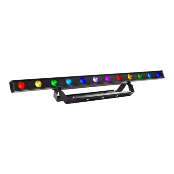
LUMIPIX12UT - 1 - INTRODUZIONE 1.1 DESCRIZIONE LUMIPIX12UT è un cambiacolori lineare, munito di 12 x 3 W RGB LED ad alta efficienza luminosa. Il sistema di gestione è personalizzabile, in linea con le esigenze di utilizzo, da 3 a 41 canali di gestione in modalità... - Page 6 LUMIPIX12UT ELETTRONICA • Dimmer: 0~100% lineare, Elettronico • Curve Dimmer: 4 Curve dimmer regolabili • Strobo/Shutter: 1/28 • Flicker: Flicker free ALIMENTAZIONE • Power Supply: 100-240V – 50/60Hz • Potenza assorbita (a 230V): 50.5W • Potenza assorbita (a 120V): 52,1W •...
-
Page 7: Elementi Di Comando E Di Collegamento
LUMIPIX12UT 1.3 ELEMENTI DI COMANDO E COLLEGAMENTI Pannello Posteriore Fig.2 1. STAFFA DI MONTAGGIO 6. POWER OUT output alimentazione per 2. MANOPOLA DI FISSAGGIO per la staffa di connessioni di più unità in serie. montaggio 7. MICROFONO per il comando tramite musica 3. -
Page 8: Montaggio
LUMIPIX12UT - 2 - INSTALLAZIONE 2.1 MONTAGGIO Il LUMIPIX12UT può essere collocato su un piano solido. Inoltre, grazie alle possibilità di fissaggio sulla doppia staffa (fig.3), l’unità può essere montata anche a testa in giù, su una traversa. Per il fissaggio oc- corrono dei supporti robusti per il montaggio. -
Page 9: Funzioni E Impostazioni
LUMIPIX12UT - 3 - FUNZIONI E IMPOSTAZIONI 3.1 FUNZIONAMENTO Per accendere il LUMIPIX12UT, inserire la spina del cavo di alimentazione in una presa di rete (110-240V~/50- 60Hz). L’unità può essere comandata da un unità DMX di comando luce oppure svolgere autonomamente il suo programma. -
Page 10: Struttura Menu
LUMIPIX12UT 3.3 STRUTTURA MENU MENU Remark ð 3 Channel Value (001-512) Default: 8 CH, d 1 ð 4 Channel Value (001-512) Default: 8 CH, d 1 ð 6 Channel Value (001-512) Default: 8 CH, d 1 ð 7 Channel Value (001-512) Default: 8 CH, d 1 ð... -
Page 11: Autoshow
LUMIPIX12UT 14 Snd ð 15 Sens Value (001-100) Default:80 ð 16 U - - Value r (000 -255) Default: RGB=255 Value g(000 -255) Value b(000 -255) ð 17 dIM Default: OFF dIM1 dIM2 dIM3 ð 18 SET Default: ON 3.4 AUTOSHOW Per entrare nella modalità... -
Page 12: Manual Color
LUMIPIX12UT • Premere ENTER per confermare la scelta. • É possibile regolare la sensibilità del microfono integrato premendo MENU fino a quando sul display non Sens. • Premere il tasto UP/DOWN per impostare il valore desiderato u0-u100, e premere il tasto ENTER per confermare la scelta. - Page 13 LUMIPIX12UT Numero Indirizzo di Indirizzo DMX Prossimo indirizzo di start Prossimo indirizzo di start Prossimo indirizzo di start canali DMX start (esempio) occupati possibile per unità n°1 possibile per unità n°2 possibile per unità n°3 33-38 33-41 33-44 DMX Address: 33 DMX Address: 42 DMX Address: 51 DMX Address: 60...
-
Page 14: Collegamenti Della Linea Dmx
LUMIPIX12UT 3.12 COLLEGAMENTI DELLA LINEA DMX La connessione DMX è realizzata con connettori standard XLR. Utilizzare cavi schermati, 2 poli ritorti, con impedenza 120Ω e bassa capacità. Per il collegamento fare riferimento allo schema di connessione riportato di seguito: DMX - OUTPUT DMX - INPUT Presa XLR Spina XLR... -
Page 15: Canali Dmx
LUMIPIX12UT 3.14 CANALI DMX 3 CANALI 7 CANALI MODE MODE FUNCTION FUNCTION Value Value 3 Ch 7 Ch 0~100% 000 - 255 0~100% 000 - 255 GREEN GREEN 0~100% 000 - 255 0~100% 000 - 255 BLUE BLUE 000 - 255 0~100% 000 - 255 0~100%... - Page 16 LUMIPIX12UT 9 CANALI MODE MODE FUNCTION FUNCTION Value Value 8 Ch 9 Ch RED 1 Color Macro 016-255 0~100% 000 - 255 Strobe GREEN 1 No Function 000 - 015 0~100% 000 - 255 Strobe slow to fast 016 - 255 BLUE 1 RGB/Auto Speed 0~100%...
- Page 17 LUMIPIX12UT MODE MODE FUNCTION FUNCTION Value Value 12 Ch 18 Ch GREEN 3 BLUE 4 0~100% 000 - 255 0~100% 000 - 255 BLUE 3 RED 5 0~100% 000 - 255 0~100% 000 - 255 RED 4 GREEN 5 0~100% 000 - 255 0~100% 000 - 255...
- Page 18 LUMIPIX12UT MODE MODE FUNCTION FUNCTION Value Value 36 Ch 41 Ch BLUE 11 BLUE 12 0~100% 000 - 255 0~100% 000 - 255 RED 12 Color Macros 0~100% 000 - 255 No Function 000 - 015 Color Macro 016 - 255 GREEN 12 Strobe 0~100%...
-
Page 19: Funzione Dimmer
LUMIPIX12UT 3.15 FUNZIONE DIMMER • Per entrare nella modalità dimmer e scegliere e simulare diverse curve dimming, premere il tasto MENU ripetutamente fino a quando sul display non compare dIM, quindi premere il tasto ENTER. • Premere il tasto UP/DOWN per selezionare OFF - dIM1 - dIM2 - dIM3. •... - Page 20 LUMIPIX12UT Per modificare l’effetto di commutazione del programma: • Premere FADE/SNAP sul telecomando. • Fade cambia lentamente l’effetto. Snap cambia rapidamente l’effetto. Per oscurare le luci: • Premere BLACK OUT sul telecomando. • Verranno spente tutte le luci fino alla successiva pressione del pulsante. NOTA - Il telecomando non risponde ad alcun input quando è...
-
Page 21: Manutenzione
LUMIPIX12UT - 4 - MANUTENZIONE 4.1 MANUTENZIONE E PULIZIA DEL SISTEMA OTTICO • Durante gli interventi, assicurarsi che l’area sotto il luogo di installazione sia libera da personale non qualificato. • Spegnere l’unità, scollegare il cavo di alimentazione ed aspettare finché l’unità non si sia raffreddata. •... - Page 22 All rights reserved by Music & Lights S.r.l. No part of this instruction manual may be reproduced in any form or by any means for any commercial use. In order to improve the quality of products, Music&Lights S.r.l. reserves the right to modify the characteristics stated in this instruction manual at any time and without prior notice.
- Page 23 LUMIPIX12UT TABLE OF CONTENTS Safety General instructions Warnings and installation precautions 1 Introduction 1. 1 Description 1. 2 Technical specifications 1. 3 Operating elements and connections 2 Installation 2. 1 Mounting 3 Functions and settings 3. 1 Operation 3. 2 Basic 3.
-
Page 24: General Instructions
LUMIPIX12UT WARNING! Before carrying out any operations with the unit, carefully read this instruction manual and keep it with cure for future reference. It contains important information about the installation, usage and maintenance of the unit. SAFETY General instruction • The products referred to in this manual conform to the European Community Directives and are there- fore marked with . -
Page 25: Introduction
LUMIPIX12UT - 1 - INTRODUCTION 1.1 DESCRIPTION LUMIPIX12UT is a linear color changer fitted with luminous high efficiency 12 x 3 W RGB LEDs. The man- agement system is customizable, in line with the user requirements, from 3 to 41 channels management mode “Pixel control”, for the independent control of each individual LED. - Page 26 LUMIPIX12UT ELECTRONICS • Dimmer: Linear 0~100% electronic dimmer • Dimmer Curves: 4 Different dimming curves available • Strobe/Shutter: 1/28 • Flicker: Flicker free operation ELECTRICAL • Power Supply: 100-240V – 50/60Hz • Power Consumption (at 230V): 50.5W • Power Consumption (at 120V): 52,1W •...
-
Page 27: Operating Elements And Connections
LUMIPIX12UT 1.3 OPERATING ELEMENTS AND CONNECTIONS Rear panel Fig.2 1. MOUNTING BRACKET 7. MICROPHONE to control the show by the 2. LOCKING KNOB for the mounting bracket external audio signal 3. SAFETY RING to attach safety cable 8. CONTROL PANEL with display and 4 button 4. -
Page 28: Installation
LUMIPIX12UT - 2 - INSTALLATION 2.1 MOUNTING LUMIPIX12UT may be set up on a solid and even surface. The unit can also be mounted upside down to a cross arm. For fixing, stable mounting clips are required. The mounting place must be of sufficient stability and be able to support a weight of 10 times of the unit’s weight. -
Page 29: Functions And Settings
LUMIPIX12UT - 3 - FUNCTIONS AND SETTINGS 3.1 OPERATION Connect the supplied main cable to a socket (110-240V~/50-60Hz). Then the unit is ready for operation and can be operated via a DMX controller or it independently performs its show program in succession. To switch off, disconnect the mains plug from the socket. -
Page 30: Menu Structure
LUMIPIX12UT 3.3 MENU STRUCTURE MENU Remark ð 3 Channel Value (001-512) Default: 8 CH, d 1 ð 4 Channel Value (001-512) Default: 8 CH, d 1 ð 6 Channel Value (001-512) Default: 8 CH, d 1 ð 7 Channel Value (001-512) Default: 8 CH, d 1 ð... -
Page 31: Auto Show
LUMIPIX12UT 14 Snd ð 15 Sens Value (001-100) Default:80 ð 16 U - - Value r (000 -255) Default: RGB=255 Value g(000 -255) Value b(000 -255) ð 17 dIM Default: OFF dIM1 dIM2 dIM3 ð 18 SET Default: ON 3.4 AUTO SHOW This fixture has a built-in automatic program. -
Page 32: Manual Color
LUMIPIX12UT 3.7 MANUAL COLOR This mode allows to combine the colors red, green, blue amber white and purple (r, g, b). • Press the button MENU so many times until the display shows [U--], then press the button ENTER. • Select the color r, g, b through the buttons UP/DOWN. •... - Page 33 LUMIPIX12UT DMX Address: 33 DMX Address: 42 DMX Address: 51 DMX Address: 60 ... . DMX512 Controller Fig.5 - Example 9 DMX channels configuration...
-
Page 34: Connection Of The Dmx Line
LUMIPIX12UT 3.12 CONNECTION OF THE DMX LINE DMX connection employs standard XLR connectors. Use shielded pair-twisted cables with 120Ω imped- ance and low capacity. The following diagram shows the connection mode: DMX - INPUT DMX - OUTPUT XLR plug XLR socket Pin1 : GND - Shield Pin2 : - Negative Pin3 : + Positive... -
Page 35: Dmx Control
LUMIPIX12UT 3.14 DMX CONTROL 3 CHANNELS 7 CHANNELS MODE MODE FUNCTION FUNCTION Value Value 3 Ch 7 Ch 0~100% 000 - 255 0~100% 000 - 255 GREEN GREEN 0~100% 000 - 255 0~100% 000 - 255 BLUE BLUE 000 - 255 0~100% 000 - 255 0~100%... - Page 36 LUMIPIX12UT 9 CHANNELS MODE MODE FUNCTION FUNCTION Value Value 8 Ch 9 Ch RED 1 Color Macro 016-255 0~100% 000 - 255 Strobe GREEN 1 No Function 000 - 015 0~100% 000 - 255 Strobe slow to fast 016 - 255 BLUE 1 RGB/Auto Speed 0~100%...
- Page 37 LUMIPIX12UT MODE MODE FUNCTION FUNCTION Value Value 12 Ch 18 Ch GREEN 3 BLUE 4 0~100% 000 - 255 0~100% 000 - 255 BLUE 3 RED 5 0~100% 000 - 255 0~100% 000 - 255 RED 4 GREEN 5 0~100% 000 - 255 0~100% 000 - 255...
- Page 38 LUMIPIX12UT MODE FUNCTION MODE FUNCTION Value 41 Ch Value 36 Ch BLUE 12 BLUE 11 0~100% 000 - 255 0~100% 000 - 255 Color Macros RED 12 No Function 000 - 015 0~100% 000 - 255 Color Macro 016 - 255 GREEN 12 Strobe 0~100%...
-
Page 39: Dimmer
LUMIPIX12UT 3.15 DIMMER • Enter in Dimmer mode to select specific dimming curve, press the button MENU so many times until shows dIM, and press the button ENTER to confirm. • Press the button UP/DOWN to select OFF - dIM1 - dIM2 - dIM3. •... - Page 40 LUMIPIX12UT • Fade will slowly switch the effect. Snap will rapidly switch the effect. To black out the lights: • Press BLACK OUT on the controller. • This will turn off all the lights until the button is pressed again. NOTE - The controller will not respond to any inputs when Black Out is activated.
-
Page 41: Maintenance
LUMIPIX12UT - 4 - MAINTENANCE 4.1 MAINTENANCE AND CLEANING THE UNIT • Make sure the area below the installation place is free from unwanted persons during setup. • Switch off the unit, unplug the main cable and wait until the unit has cooled down. •... - Page 44 MUSIC & LIGHTS S.r.l. Via Appia, km 136,200 - 04020 Itri (LT) - ITALY Phone +39 0771 72190 - Fax +39 0771 721955 www.musiclights.it - email: info@musiclights.it ISO 9001:2008 Certified Company...
Need help?
Do you have a question about the TRIBE LUMIPIX12UT and is the answer not in the manual?
Questions and answers