Table of Contents
Advertisement
Quick Links
PONOVO POWER CO., LTD
2F, 4Cell, Tower C, In.Do Mansion
No.48A Zhichun Road, Haidian District
Beijing, China (Post Code 100098)
Office
TEL. +86 (10) 82755151-8887
FAX +86 (10) 82755257
E-Mail Info@relaytest.com
Website www.relaytest.com
VERSION:
DATE:
This manual is the publication of PONOVO POWER CO., LTD. Any form of copy needs
to be consent by PONOVO POWER CO., LTD.
This manual represents the technical status for the moment of publishing. The product
information, description and specifications mentioned in the manual do not have any
contact binding force and PONOVO POWER CO., LTD remains the right to make
modifications to the technical specifications and configurations without prior notice.
PONOVO does not take responsibility to the possible error/mistakes in this manual.
TD4000A
HARDWARE USER MANUAL
TD4000A-AE-1.02
26/06/2012
1
TD4000A Hardware User Manual
Advertisement
Table of Contents

Related Manuals for Ponovo TD4000A


Summary of Contents for Ponovo TD4000A
- Page 1 TD4000A-AE-1.02 DATE: 26/06/2012 This manual is the publication of PONOVO POWER CO., LTD. Any form of copy needs to be consent by PONOVO POWER CO., LTD. This manual represents the technical status for the moment of publishing. The product information, description and specifications mentioned in the manual do not have any contact binding force and PONOVO POWER CO., LTD remains the right to make...
- Page 2 TD4000A Hardware User Manual Notes: In order to prevent static electricity, the tester must be connected to ground before testing. Please note personal and equipments safety while equipment outputs large current. Avoid short circuit or connecting load while testing. Avoid external voltage and current being added at the output of equipments.
-
Page 3: Table Of Contents
TD4000A Hardware User Manual Content General Description ....................Panel Description ..................... Technical specifications ..................Output and Input ..................... Binary input ..................... Binary output ....................3.4 LED........................Power input ..................... 3. 6 Dimension and weight ..................Environmental conditions ................Operation Instructions ..................... -
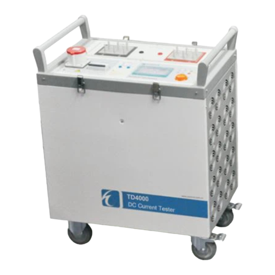
Page 4: General Description
TD4000A Hardware User Manual 1. General Description TD4000A consists of control unit and DC current output unit. The 100-4000A 0.1% high precision programmable DC current is used for characteristics testing in Special high- voltage DC converter station, DC current transformer, control and protection. - Page 5 TD4000A Hardware User Manual Run lamp: output indicator Over-heat indicator: The lamp alarms and flashes when the temperature of internal power model is above 80 ℃ and output is cut. Over load indicator: The lamp flashes when the current and voltage are over-loaded, and manually stops the output.
-
Page 6: Technical Specifications
TD4000A Hardware User Manual 3. Technical specifications 3.1 Output and Input Model TD4000A Output range 0~4000A Accuracy ±0.1% Port voltage 5.0V Max. output time 1000A 2000A 4000A at full current Continuous 240 s 60 s load 10%-99%raising 0A-4000A time 20 ms... -
Page 7: Binary Input
TD4000A Hardware User Manual 3.2 Binary input The two independent input ports can judge the circuit and space contact is compatible with 30V-250V potential. It is auto identification and time accurate of 1ms(0.001-1s), ±0.1% (1-999.999s). Figure 1.2 3.3 Binary output One pair;contact rating:250V DC/0.5A、250V AC / 8A... -
Page 8: Dimension And Weight
TD4000A Hardware User Manual 3. 6 Dimension and weight Dimension:660mm x 450mm x 880mm(L*W*H) Weight:110kg 3.7 Environmental conditions Temperature: 0℃~40℃ Relative humidity: ≤90% non-condensing Atmospheric pressure: 86kPa~106kPa... -
Page 9: Operation Instructions
TD4000A Hardware User Manual 4. Operation Instructions 4.1 Select test functions There are four buttons F1, F2, F3 and menu in the test unit area. Choose main menu button at any interface to enter the main menu. Entering the main menu, rotate ENTER button to select the test function and push the ENTER go to specified function. -
Page 10: Choose Variables
TD4000A Hardware User Manual 4.2 Choose variables Entering the test menu, rotate ENTER button to select variable. The selected operation is displayed in black with background of white. 4.3 Set test parameters Change variable parameter by pushing ENTER button and rotating it clockwise and counterclockwise. -
Page 11: Check And Save Test Report
TD4000A Hardware User Manual 4.5 Check and save test report 4.5.1 Check test report The saved test report can be checked by entering the report check interface. Ten reports can be displayed in each page and 30 reports can be stored. “1/3” means that there are three pages and the present is the first page. -
Page 12: System Settings
TD4000A Hardware User Manual 4.6 System settings Screen backlight, buzzer and time can be set by choosing main menu system settings. -
Page 13: Test Functionality Instructions
TD4000A Hardware User Manual 5. Test functionality instructions In this unit, maximum 4000A can be output manually. The current amplitude and output time can be controlled; the action time can be measured here. The following is the main menu of the set. -
Page 14: Manual Test
TD4000A Hardware User Manual 5.1 Manual test This unit can put out current of 4000A at maximum, which can control current amplitude and output time manually and test opening time. This is the operation interface: Connect the cables as followings:... - Page 15 TD4000A Hardware User Manual Set current and time, and output time will be shown real-timely after run. Iout and Uout will be shown which are the real output current and voltage. The set current will be put out by pushing RUN button and it stops output when ...
-
Page 16: Pc Control
TD4000A Hardware User Manual 5.2PC Control Main functions of PC Control test are: transmitting test report to PC and test step grading and state sequence. -
Page 17: Accessories
TD4000A Hardware User Manual 6. Accessories 250 fixture:2 sets【It is used for testing bus cable with diameter of 250mm, seeing the installation below.】 50 fixture:10 sets【It is used for testing bus cable with diameter of 50mm, seeing the installation below.】... - Page 18 TD4000A Hardware User Manual 30 bush : 12 sets 【Work with 50 fixture. It is used for testing bus cable with diameter of 30mm, seeing the installation below.】 4000A installation bus bar:12 pieces. 10M: 6 pieces; 6M: 6 pieces【It is used for...
- Page 19 TD4000A Hardware User Manual 2 wrenches Power cord Yellow green (or Yellow, green, red Blue black) L1、L2、L3(no phase Zero line N Earth wire sequence)...
- Page 20 TD4000A Hardware User Manual High-intensity air box: 3. It is used to pack the accessories.
- Page 21 TD4000A Hardware User Manual Bus dedicated connector (Optional) The position placed in the package: There are two floors. In the first floor, there is 250 fixture. In the second floor, there are 50 and 30 fixture.
-
Page 22: Installation Of Test Fixture
TD4000A Hardware User Manual 7. Installation of test fixture 1). (Bus bar) Diameter is 250mm. First clean the bus where the fixtures are installed, and connect 250 fixture and bus cables showing in the picture. Fasten the connection with screw nut, showing below:... - Page 23 TD4000A Hardware User Manual 2). (Bus bar) Diameter is 50mm. First clean the bus bar where the fixtures are installed, and connect 50 fixture and the tested bus bar showing in the picture. Fasten the connection with screw nut. If there are several bus cables, 4 bus cables with diameter of 50mm can be connected to the bus cables’...
- Page 24 TD4000A Hardware User Manual 3). (Bus bar) Diameter is 30mm. First clean the bus bar where the fixtures are installed, and put bushing 30mm into fixture 50mm and the tested bus bar. Installed as the following: Fasten the connection with screw nut. If there are several bus cables, 4 bus cables with diameter of 50mm can be connected to the bus cables’...
Need help?
Do you have a question about the TD4000A and is the answer not in the manual?
Questions and answers