Table of Contents
Advertisement
Quick Links
PW460 Hardware Instruction Manual
PONOVO POWER CO., LTD
7478 Kilbrittain Ln, Dublin, OH 43017, US
TEL. 614-401-8641
Office
yxue@flexgridapp.net
E-Mail
www.flexgridapp.net
Website
VERSION:
DATE :
This manual is the publisher of PONOVO POWER CO., LTD. To make any kind of copy of this
manual please contact PONOVO POW ER CO., LTD in advance.
This manual represents the technical status for the moment of publishing. The product information,
description and specifications mentioned in the manual do not have any contact binding force and
PONOVO POW ER CO., LTD remains the right to make modifications to the technical
specifications and configurations without prior notice. PONOVO POW ER does not take
responsibility to the possible error/mistakes in this manual.
www.flexgridapp.net
PW460
HARDWARE INSTRUCTION MANUAL
PW460-AE-3.22
11/15/2017
1
Advertisement
Table of Contents

Related Manuals for Ponovo PW460


Summary of Contents for Ponovo PW460
- Page 1 DATE : 11/15/2017 This manual is the publisher of PONOVO POWER CO., LTD. To make any kind of copy of this manual please contact PONOVO POW ER CO., LTD in advance. This manual represents the technical status for the moment of publishing. The product information, description and specifications mentioned in the manual do not have any contact binding force and PONOVO POW ER CO., LTD remains the right to make modifications to the technical...
-
Page 2: Table Of Contents
PW460 Hardware Instruction Manual Contents ……………………………………..23 1. Preface ……………………… 9. PW460-Related Products and 2. Safety precaution …………. Accessories…………………… 26 3. Designed applications …… 9.1 PGPS02-GPS-based Synchronization 4. Operation preparation …… device …….…………………………… 27 4.1 Preparation …………………. 9.2 PIRIG-B Based Synchronization 4.2 Connecting PC …………….. -
Page 3: Preface
PW460 Hardware Instruction Manual 1.Preface This manual gives detailed introduction to At the test site user should also refer to other PW460 so that user can have the reasonable, safety and test regulations required by his effective and safe operation of this test kit. -
Page 4: Safety Precaution
PW460 Hardware Instruction Manual 2.Safety Precaution In case the power outlet for powering up the PW460 don’t have protective ground customer must connect the ground socket of PW460 to the protective ground at the test site Please turn off the output before connecting/disconnecting the test object The voltage output of over 36V is considered as dangerous and care must be taken It’s not allowed to feed external voltage into the voltage/current output sockets... -
Page 5: Designed Applications
PW460 Hardware Instruction Manual 3.Designed Applications Product Features PW460 can be used by power plants, substations, and relay manufactures, etc., for the following test applications. Output sources 6×15A current sources in two groups Test protective relays 4×300V voltage sources... -
Page 6: Operation Preparation
PW460 Hardware Instruction Manual 4.Operation Preparation Preparation Be sure that the following preparation/system components are ready before operating the test equipment: PW460 test equipment Main supply cable (delivered) LAN control cable (delivered) PC with PowerTest software properly installed ... -
Page 7: General Description
PW460 Hardware Instruction Manual 5.General Description Block Diagram DSP Card High performance DSP (digital signal processor) is used on the DSP card to ensure the accurate and fast signal generation. To get the satisfied accuracy and resolution the 32 bit D/A data converting technology is applied. -
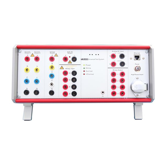
Page 8: Front Panel
PW460 Hardware Instruction Manual Front Panel Current output group 1 Binary input group 1 Current output group 2 LED indication Voltage output Earth socket Auxiliary DC 10. Binary output group 1 DC measuring input 11. Pause button RJ45 Ethernet PC control port 12. -
Page 9: Current Booster Interface
PW460 Hardware Instruction Manual Current Booster Interface This interface is used to connect to the external current booster (optional) for testing high burden relays. Signal Current IA Current IN Current IB Current IN Current IC Current IN Current Ia Current In... -
Page 10: Pause Button
PW460 Hardware Instruction Manual Please refer to “Current booster user manual” for details Pause Button The Pause button on the front panel is designed to cut the current/voltage outputs either for test purpose or under emergency case. ‘Manual’ control mode ‘Auto’... -
Page 11: Rear Panel
PW460 Hardware Instruction Manual Rear Panel Binary input group 2 Multi-kits synchronization interface Binary output group 2 IP reset Low level output interface Connector for mains supply Ventilation Power switcher GPS interface External Amplifier and Low level Output Interface This interface is used to connect to external amplifier (optional) to increase the output channel and output power. - Page 12 PW460 Hardware Instruction Manual Signal Low level output 1 Low level output 2 Low level output 3 Low level output 4 Low level output 5 Low level output 6 Low level output 7 Low level output 8 Low level output 9...
-
Page 13: Gps Interface
PW460 Hardware Instruction Manual GPS Interface This interface is used to connect to our optional PGPS02 GPS-based synchronization device. Signal Contact pin Power Ready DB9 Chassis contact, male ---------------------------------------------- Note: PPS means Pulse Per Second ---------------------------------------------- One popular application of GPS-synchronized control is for end-to-end test for line protection relay Please refer to ‘PGPS02 user manual’... -
Page 14: Multi-Kits Synchronization Interface
PW460 Hardware Instruction Manual Multi-kits Synchronization Interface This interface is used to connect more relay test kits for synchronized control. In synchronized control mode only one PC is required to control all relay test kits. Point-by point synchronization is used to ensure the synchronization accuracy. -
Page 15: Ip Reset
PW460 Hardware Instruction Manual IP Reset This reset button is used to restore the IP address of PW460 to the default factory setting. Press this button Switching on the power for PW460 After this operation the IP address will be restored to the following settings. -
Page 16: Hardware Configuration
PW460 Hardware Instruction Manual 6.Hardware Configuration Current Generators Test modules which requires 6 current mode configuration PW460 has 6 current generators in two groups. General QuickTest They can be configured as either 3 currents QuickTest (4V,6I) mode or 6 current mode. - Page 17 PW460 Hardware Instruction Manual Range 3-phase ac (L-N) 3 × 0 … 30 A 1-phase ac (3L-N) 1 × 0 … 90 A 1-phase ac (L-L) 1 × 0 … 30 A 1-phase dc (L-N) 1 × 0 … 20A 1-phase dc (3L-N) 1 ×...
-
Page 18: Current In Series Connection In 3 Current Mode
PW460 Hardware Instruction Manual Current in Series Example: Settings in QuickTest (4V, 3I) for IA and IB in series connection Connection in 3 Current Mode In 3 current mode the two current generators can be connected in series to increase the compliance voltage. -
Page 19: Voltage Generators
PW460 Hardware Instruction Manual Voltage Generators PW460 has 4 voltage generators. ---------------------------------------------- Note: The maximum voltage output will become 600Vac in this case ---------------------------------------------- Connect Two Voltage Generators in Series We can connect two voltage generators in series to get higher voltage output range. -
Page 20: Binary Inputs And Outputs
PW460 Hardware Instruction Manual 7.Binary Inputs and Outputs General Description Binary Input PW460 has 8 binary inputs in two groups. The device has 8 binary inputs. Electricity is isolated in A-H. Space contact or active The first group of 4 binary inputs (A, B, C, D) contact (15V-250V) can be set by software. -
Page 21: Polarity Of Binary Inputs
PW460 Hardware Instruction Manual Polarity of Binary Isolation of the Inputs Binary Inputs The polarity reference of the binary inputs is shown below. All 8 binary inputs are galvanically isolated from each other. Binary configuration The software interface for binary configuration (A-H) shows below. -
Page 22: Binary Outputs
PW460 Hardware Instruction Manual At the rear side of the kit there are Binary Outputs another 4 binary outputs 5-8. PW460 has 8 binary outputs in two groups The binary outputs 1-4 are placed on the front panel. These 4 binary outputs are high speed semiconductor type. -
Page 23: Getting Ready For Pc Controlled Operation
2~254 (except 133). Steps for setting IP address for computer. PowerTest test software must be properly installed on the PC to control PW460. The Step 1: Left click ‘Start/Control panel/Network installation description of PowerTest test connection’... - Page 24 PW460 Hardware Instruction Manual Step 2: Right click ‘Local connection’ icon Step 3: Left click the ‘Properties’ ---------------------------------------------- Note: the last section of IP address can be any number between 2-254 (except 133) ---------------------------------------------- Step 5: Make the settings ...
- Page 25 PW460 Hardware Instruction Manual If we see the following display on the right Check if control cable is connected bottom corner then we need to make the Check if PW460 is powered up check as mentioned bellow Check if IP address is set properly www.flexgridapp.net...
-
Page 26: Pw460-Related Products And Accessories
PW460 Hardware Instruction Manual 9.PW460-Related Products and Accessories This chapter describes the optional equipment and accessories for the PW460 test set. Please visit the PONOVO Web site www.flexgridapp.net for up-to-date information. Optional accessories Standard accessories Item Part No. PGPS02 GPS based... -
Page 27: Pgps02-Gps-Based Synchronization Device
IRIG-B time inputs. reference signal (DC level shift protocol B00x). That way, two or more PONOVO test sets are For detailed information about the PGPS, synchronized. please refer to the PGPS User Manual, the... -
Page 28: Pss01 Circuit Breaker Simulator
PW460 Hardware Instruction Manual 9.3 PSS01 Circuit Breaker 9.4 Phpc01 Current Booster Simulator Phpc01 current booster is designed to supply high compliance voltage even at small current t can simulate circuit breaker behaviors in range, suitable for testing high burden three pole or 1 pole tripping of 6-500KV electromagnetic current relays. -
Page 29: 9.5 Pacb108 Scanning Head
SAW 0016/SAW 0017 Fiber Optic Cable Sampling distance: 10-30 mm 2xorange-MTRJ-ST 2xorange-MTRJ-MTRJ Maximum sampling pulse: 100 pulses/second When PW460 is connected with a fiber 9.6 Low Level Output and switcher, fiber optic cables are required. Counter Input Cable SAW 0014 This cable is used to connect amplifiers with PONOVO kit. -
Page 30: 9.9 Standard Accessories
PW460 Hardware Instruction Manual 9.9 Standard Accessories 9.9.1 Soft Bag for Test Leads The PW460 Wiring Accessory Package contains the following articles: 1. Color coded current cables SAW 0201/ 0203 color coded current cable 2xred, 2xblack, 2xyellow, 2xblue xred, 1xblack, 1xyellow, 1xblue... - Page 31 PW460 Hardware Instruction Manual Color coded voltage cables SAW 0202 Color coded voltage cable Amount: 1x red, 1x yellow, 1x green, 1x blue, 1x black The voltage cables to connect the PW 460 output to other safety sockets of, generally the voltage parts, current and signal tripping.
- Page 32 PW460 Hardware Instruction Manual Flexible Terminal Adapter SAW 0206 Flexible terminal adapter Amount: 10xred, 10xblack Flexible terminal adapter connects to screw-clip terminals. -------------------------------------------------------------------------------------- Notes: One end of the adapters have no Users insert the non-safety into the insulator, users should make sure there is terminals and screw it firmly, then connect no output during connecting the adapters.
- Page 33 PW460 Hardware Instruction Manual Jumper Cable SAW 0207 Flexible jumpers Amount: 4xblack Flexible jumper connects current outputs in parallel. Crocodile Clips SAW 0208 Crocodile clips Amount: 2xred, 2xblack, 2xyellow, 2xblue Crocodile clips for secondary side to connect to pins or screw types.
- Page 34 PW460 Hardware Instruction Manual SAW 0209 U clamps 1# SAW 0210 U clamps 2# Amount: 10xred, 10xblack 5xred, 5xblack It is used to connect test leads with screw type terminals. ------------------------------------------------------------------------------------------ Notes: One end of the adapters have no insert the non-safety into the terminals and...
- Page 35 9. Power Cord SAW 0009 Power code Amount: 1 piece Power cord connects the PW 460 with power supply socket. PONOVO will provide relevant plug socket according to different countries. For the plug socket information, please check the Chapter 11. Appendix. www.flexgridapp.net...
- Page 36 PW460 Hardware Instruction Manual 10. Earthing Lead SAW 0018 Earthing lead Specification: 2.5mm²×4m Amount: 1 piece Earthing lead connects the PW 460 with ground to ensure kit safety. ----------------------------------------------------------------------------------------- Notes: In order to avoid static induction, users reliably before testing.
-
Page 37: 9.7.2 Transportation Case
PW460 Hardware Instruction Manual 9.7.2 Transportation Case The large-size case with wheels is designed for heavy transport stress with folding hand it is made of fireproof materials and smooth rolling rubber tires. SAC0105 Transportation case Dimension: 465x250x525mm (WxHxD) Weight: 10Kg. -
Page 38: Specifications
PW460 Hardware Instruction Manual 10.Specifications Voltage Generators or potential free Sample rate 20kHz Setting range Time resolution 50µs 4-phase ac (L-N) 4 × 0-300V Max. measuring time infinite 1-phase ac (L-LL) 1 × 0-600V De-bounce/Deglitch time 0- dc (L-N) 4 × 0-±300V... - Page 39 PW460 Hardware Instruction Manual Active/reactive power error < 1% rg. typ. Resolution 250uV Monitoring Distortion 0.05% typ (0.1% guar) Channel number Connection 19 pin combination socket Mode monitoring the output (rear side) voltage/current waveform during the test process Power supply...
- Page 40 PW460 Hardware Instruction Manual Environmental condition Operating temperature 0-+50°C Storage temperature -25-+70°C Relative humidity 5-95%, non-condensing EMC (Emission) IEC-61000-3-2/3 EMC (immunity) IEC-61000-4-2/3/4/5/6/11 Safety IEC 61010-1 Others PC-Connection Ethernet, 10M/100Mbps Amplifier interface Circular connector Current booster interface Circular connector Synchronization interface Coaxial cable connector...
-
Page 41: Appendix
PW460 Hardware Instruction Manual 11.Appendix In order to assure PONOVO sockets are used smoothly in foreign countries, PONOVO provides the plug sockets to our customers in different countries. The followings are the sockets used in different countries. 1. Plug Type B Type B adapter is mainly used in America, Canada and Taiwan etc. - Page 42 PW460 Hardware Instruction Manual 2. Plug Type I Adapter The UK type plug is mainly used in United Kingdom, India, Pakistan, Thailand, Malaysia, Singapore, New Zealand and Hong Kong etc. 3. Plug Type L Adapter Type L Adapter is mainly used in South Africa and British Standard 15A.
- Page 43 PW460 Hardware Instruction Manual 4. Plug Type N Adapter This adapter is mainly used in Italy. 5. Type G Adapter Type G Adapter is mainly used in German, Finland, France, Norway, Sweden, Poland, South Korean, Austria, Spain, Hungary, Czech, Ukraine, Turkey, Brazil and Russia etc.
Need help?
Do you have a question about the PW460 and is the answer not in the manual?
Questions and answers