Table of Contents
Advertisement
PONOVO POWER CO., LTD
No. 139 Jinghai Third Road, BDA, Beijing, China, 100176
Office
TEL. +86 (10) 59089666
E-Mail
Info@relaytest.com
Website
www.relaytest.com / www.ponovo.com.cn
PCT200 Series User Manual
VERSION:
DATE:
This manual is the publication of PONOVO POWER CO., LTD. Any form of copy should obtain the
consent of it.
This manual represents the technical status for the moment of publishing. The product information,
description and specifications mentioned in the manual do not have any contact binding force and
PONOVO POWER CO., LTD remains the right to make modifications to the technical
specifications and configurations without prior notice. PONOVO POWER PONOVO explicitly
exonerates itself from all liability for mistakes in this manual
PCT200 Series CT/PT Test System User Manual
PCT200 -AE-1.04
JUNE 2017
1
Advertisement
Table of Contents

Related Manuals for Ponovo PCT200 Series


Summary of Contents for Ponovo PCT200 Series
- Page 1 PCT200 -AE-1.04 DATE: JUNE 2017 This manual is the publication of PONOVO POWER CO., LTD. Any form of copy should obtain the consent of it. This manual represents the technical status for the moment of publishing. The product information, description and specifications mentioned in the manual do not have any contact binding force and PONOVO POWER CO., LTD remains the right to make modifications to the technical...
- Page 2 PCT200 Series CT/PT Test System User Manual Notes: In order to prevent static electricity, the PCT and test CT must be connected to ground safely before test. Avoid electric shock accident when the output voltage is above 36V. Short circuit is prohibited at output side while testing.
- Page 3 PCT200 Series CT/PT Test System User Manual Special Tips: 1. CT/PT testing system (called PCT) is applied in the electromagnetic and low leakage flux current transformer (CT without gapped core or compensation) and inductive voltage transformer (PT) of power system. It completes the following test items: ...
- Page 4 PCT200 Series CT/PT Test System User Manual 5. It is prohibited to maintain reform, extend or change the system or any other accessories. 6. Only original accessories are accepted in test and detection process. 7. Do not switch-on and operate PCT in the place having explosive gas or water vapor 8.
-
Page 5: Table Of Contents
PCT200 Series CT/PT Test System User Manual Content 1. General Description ........................7 1.1 Functions ........................... 7 1.2 Technical Specifications ..................... 9 1.3 Features .......................... 10 1.4 Operation Preparation ..................... 12 1.5 Block Diagram ......................... 13 2. Panel Description ........................14 3. - Page 6 PCT200 Series CT/PT Test System User Manual 5.3.4 Bushing CT Test ....................... 49 5.3.5 Test CT with Tapping ......................50 6. PT test ..............................51 6.1 Wiring Connection ........................51 6.1.1 Polarity and Ratio Test ..................... 51 6.1.2 Excitation Test ........................53 6.2 Test Operation ..........................
-
Page 7: General Description
PCT200 Series CT/PT Test System User Manual 1. General Description 1.1 Functions PCT200i PCT200Ai CT type P, TP, M P, TP, M(0.2S) ◆ ◆ Ratio, polarity ◆ ◆ Coarse ratio ◆ ◆ Guess ratio ◆ ◆ Turn-ratio and error Ratio error and phase ◆... - Page 8 PCT200 Series CT/PT Test System User Manual ◆ Symmetrical short-circuit current ◆ ratio (Kssc) Peak instantaneous (total) error εˆ ◆ ◆ △ △ Guess nameplate ◆ ◆ Report tools △ △ Ratio ◆ ◆ Polarity △ △ Excitation characteristic Notes: The symbol “...
-
Page 9: Technical Specifications
PCT200 Series CT/PT Test System User Manual 1.2 Technical Specifications Items PCT200i PCT200Ai Output voltage range 0-120V Output current range 0-5Arms (15A peak) Output power 0.0001-500VArms (1500VA peak) Ratio test range 30,000:1-45,000:5 1-2,000 0.05% Typ. 0.10%Gur 1-2,000 0.02% Typ. 0.05%Gur Ratio test accuracy﹡... -
Page 10: Features
PCT200 Series CT/PT Test System User Manual 1.3 Features Apply the newest principle of multi point DC method and meet the standard of IEC 44-6 The voltage measurement of ratio and phase displacement complies with standard of IEC 61869-2. - Page 11 PCT200 Series CT/PT Test System User Manual User-defined test according to the defined standards. PT test items: ratio, polarity and volt-ampere characteristic.
-
Page 12: Operation Preparation
PCT200 Series CT/PT Test System User Manual 1.4 Operation Preparation Preparation: CT secondary side load loop disconnection and secondary winding off-grounded CT primary side disconnects with busbar Order of connection: 1. The chassis of PCT is grounded. 2. One end of CT primary side grounded (P2) Note: There is a grounding switch in one side of primary. -
Page 13: Block Diagram
PCT200 Series CT/PT Test System User Manual 1.5 Block Diagram... -
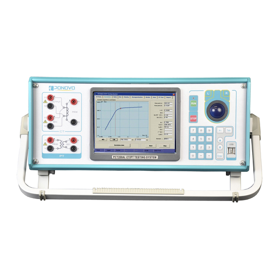
Page 14: Panel Description
PCT200 Series CT/PT Test System User Manual 2. Panel Description Connecting CT secondary side Secondary side voltage test while testing CT/PT (PT Excitation only) Primary side voltage test while testing CT Connecting PT primary side Secondary side voltage test while testing PT... -
Page 15: Operation Instruction
PCT200 Series CT/PT Test System User Manual 3. Operation Instruction 3.1 Select Test Functions Choosing main menu button at any interface to enter, then rotating rotary encoder to change the cursor position and select specified testing button. The selected operation is displayed in the... -
Page 16: Set Test Parameters
PCT200 Series CT/PT Test System User Manual 3.2 Set Test Parameters Set variable parameters by pushing keyboard and pressing mouse. 3.3 Control Output The run and stop buttons on the panel or the start test and stop test functions can control the output. - Page 17 PCT200 Series CT/PT Test System User Manual Synchronize CT Report: Synchronize today’s or all the reports into mobile disc showing below. Save CT Report: Save the reports to Disc D. Synchronize PT Report: Synchronize today’s or all the reports into mobile disc showing below.
- Page 18 PCT200 Series CT/PT Test System User Manual Report folder: Select the report folder to be synchronized. Target folder: Select the folder to save the synchronized reports. Synchronize Folder: Synchronize all the reports in the folder. Sync today’s CT/PT report: Synchronize the day’s CT/PT reports.
-
Page 19: Pct Report Tools User Manual
PCT200 Series CT/PT Test System User Manual 3.5 PCT Report Tools User Manual Figure 1 Figure 2 In figure 1, it is the PC software interface installed Excel. In figure 2, it is the PC software interface without Excel or in the PCT system. - Page 20 PCT200 Series CT/PT Test System User Manual Files: 1. open files: open the PCT report (ini format) When the single file or less than 7 files are opened, it directly superposes the pictures and the selected files are listed in the open file list. When more than 6 files are selected to open, it will not open the pictures automatically.
- Page 21 PCT200 Series CT/PT Test System User Manual Save excel report: to save excel reports If there is only one opened report, the report is the same as the test excel report and its name is similar to the PCT files.
- Page 22 PCT200 Series CT/PT Test System User Manual The following is sampling Excel format report, A4.
- Page 23 PCT200 Series CT/PT Test System User Manual...
- Page 24 PCT200 Series CT/PT Test System User Manual...
- Page 25 PCT200 Series CT/PT Test System User Manual Back: back to the main interface Exit: exit the program. Open file list: to list the open reports, files name and open serial number. The successfully opened reports are displayed in red and the check boxes are selected. The reports waiting for open are displayed in black and the check boxes are not selected.
- Page 26 PCT200 Series CT/PT Test System User Manual Settings: set the present report The number keys are switched the present open reports. Double click to change the page script.
- Page 27 PCT200 Series CT/PT Test System User Manual Result: display the present test results The number keys are switched the opened reports. Double click to change the page script.
- Page 28 PCT200 Series CT/PT Test System User Manual V-A Curve: excitation curve analysis Right-click menu (Back ground color): correct the curve background color Right-click menu (Add user data): add the user data of each curve. The number keys can choose one curve to display on the top and the lines are bold.
- Page 29 PCT200 Series CT/PT Test System User Manual...
- Page 30 PCT200 Series CT/PT Test System User Manual...
-
Page 31: Burden Test
PCT200 Series CT/PT Test System User Manual 4. Burden Test 4.1 Wiring Connection Connecting the instrument transformer according to the below direction, while doing secondary load impedance test. Wiring direction: The transformer’s output end S1 and testing end S1 are connected with one side of secondary load the CT. -
Page 32: Test Operation
PCT200 Series CT/PT Test System User Manual 4.2 Test Operation Entering the main menu and selecting the Rct/polarity/demagnification/load impedance test unit, CT secondary burden measuring can be done. After entering this unit and moving the mouse in the load impedance testing zone, the test software button is automatically available. The load impedance test can be finished pressing start button. -
Page 33: Ct Test
PCT200 Series CT/PT Test System User Manual 5. CT Test 5.1 Wiring Connection While doing the CT secondary coil resistance, polarity, excitation, demagnetization and ratio test, the instrument transformer tester should be connected according to the below diagram. Wiring direction: The transformer’s output S1 and testing side S1 are connected with one side of CT secondary. - Page 34 PCT200 Series CT/PT Test System User Manual The comparison between four-cable and two-cable testing: The transformer secondary tap is connected by claps and the following four-cable connection is applied. Four-cable connection Two-cable connection Otherwise, the chuck resistance might affect measuring result and the CT tester might list the incorrect measuring result.
-
Page 35: Test Operation
PCT200 Series CT/PT Test System User Manual 5.2 Test Operation 5.2.1 Settings Select CT parameter setting menu after entering into main menu. The CT nameplate parameters can be set by mouse or keyboard. The testing result will be correct on condition that the settings are right. - Page 36 PCT200 Series CT/PT Test System User Manual...
- Page 37 PCT200 Series CT/PT Test System User Manual TPY type CT parameter setting:...
- Page 38 PCT200 Series CT/PT Test System User Manual M type CT parameter setting:...
-
Page 39: Rct Measuring
PCT200 Series CT/PT Test System User Manual 5.2.2 Rct Measuring CT secondary winding resistance test can be done after selecting the Rct/Polarity/Demagnet/ Burden measuring unit. Entering the Rct measuring unit, the secondary winding Rct can run automatically after pressing the run button. The measuring result 25 degrees celsius means the resistance at current temperature and the 75 degrees celsius means the resistance at 75 degrees celsius. -
Page 40: Demagnetization
PCT200 Series CT/PT Test System User Manual 5.2.3 Demagnetization CT demagnetization can be done after selecting the Rct/Polarity/Demagnet/ Burden unit. The process will automatically run when entering the unit and pushing the run button. After the process, it will automatically stop and the lamp is off. -
Page 41: Polarity Test
PCT200 Series CT/PT Test System User Manual 5.2.4 Polarity Test CT polarity check can be done after selecting the Rct/Polarity/Demagnet/ Burden unit. The polarity test is automatically finished while pushing the run button. It stops automatically and the lamp is off. The test method is negative polar. -
Page 42: Excitation Test
PCT200 Series CT/PT Test System User Manual 5.2.5 Excitation Test CT excitation test can be done after selecting the Excita. unit. The test will automatically run while entering the Excita. unit. It stops automatically after test and the lamp is off. - Page 43 PCT200 Series CT/PT Test System User Manual Red cross will be shown at the knee point. Press Cursor left, Cursor right or put in figures related to the value to observe. Press excitation button, the excitation curve can be changed into data table pressing V-A data to...
-
Page 44: Ratio Test
PCT200 Series CT/PT Test System User Manual 5.2.6 Ratio Test CT ratio test can be made in Ratio test. CT ratio, ratio error, phase displacement, composite error and turns ratio error can be automatically tested. When the test is completed, it stops automatically and the lamp is off. -
Page 45: Auto Test
PCT200 Series CT/PT Test System User Manual 5.2.7 Auto Test CT excitation, polarity, ratio, secondary side winding resistance and demagnetization tests all can be done after selecting auto test unit and pushing run button. When it is finished, the test automatically stops and the lamp is off. -
Page 46: Application Examples
PCT200 Series CT/PT Test System User Manual 5.3 Application Examples 5.3.1 Transmission line CT Test... -
Page 47: Ct Test In Y Voltage Transformer
PCT200 Series CT/PT Test System User Manual 5.3.2 CT Test in Delta Connection Transformer In order to reduce interference, other windings of the CT transformer should be short circuit. -
Page 48: Ct Test In The Star Connection Voltage Transformer
PCT200 Series CT/PT Test System User Manual 5.3.3 CT Test in the Star Connection Transformer In order to reduce interference, other transformer’s windings should be short circuit. -
Page 49: Bushing Ct Test
PCT200 Series CT/PT Test System User Manual 5.3.4 Bushing CT Test In order to reduce interference, other windings of the CT transformer should be short circuit. -
Page 50: Test Ct With Tapping
PCT200 Series CT/PT Test System User Manual 5.3.5 Test CT with Tapping All the windings in the same shank are all switched on while testing CT with tapping. -
Page 51: Pt Test
PCT200 Series CT/PT Test System User Manual 6. PT test 6.1 Wiring Connection 6.1.1 Polarity and Ratio Test Connect instrument transformer tester as illustrated in below when doing PT polarity, ratio test. Wiring directions:The output “A” of transformer is connected with one side of PT primary. - Page 52 PCT200 Series CT/PT Test System User Manual Note: The wiring for primary and secondary cannot be wrong, otherwise, it may give thousands of voltage.
-
Page 53: Excitation Test
PCT200 Series CT/PT Test System User Manual 6.1.2 Excitation Test Connect transformer tester as illustrated in below when doing PT excitation test. Single-phase voltage transformer Three-phase voltage transformer Wiring directions: The output S1 of PCT is connected with one side of PT secondary. -
Page 54: Test Operation
PCT200 Series CT/PT Test System User Manual 6.2 Test Operation 6.2.1 Settings Set parameters according to PT nameplate. -
Page 55: Polarity And Ratio Test
PCT200 Series CT/PT Test System User Manual 6.2.2 Polarity and Ratio Test The PT polarity, ratio test can be automatically finished after selecting polarity ratio and pushing run button. It stops automatically and the lamp is off. -
Page 56: Excitation Test
PCT200 Series CT/PT Test System User Manual 6.2.3 Excitation Test Enter into PT test unit, and then choose excitation test. Every voltage and current value can be checked in the excitation curve. Press Save button to save the testing report after finished the test. - Page 57 PCT200 Series CT/PT Test System User Manual 7. Assessment In the CT Parameter Assess areas, the assessment items will be automatically activated according to the test CT type and standards.
- Page 58 PCT200 Series CT/PT Test System User Manual In this case the FS is 5 on the CT nameplate, but the FS>4.016. It means while making this kind of CT, the PCT can only test FS at 4.016 times, but can’t get the exact FS value.
- Page 59 PCT200 Series CT/PT Test System User Manual In this case, the test engineer can decide to pass or fail the result separately and save the assessment report.
-
Page 60: Appendix: Glossary
PCT200 Series CT/PT Test System User Manual 8. Appendix: Glossary CT: current transformer PT: Voltage transformer P/TP/M: the type of CT. protection current transformer class P M: measurement current transformer PR: protection current transformer class PR PX: protection current transformer class PX... - Page 61 PCT200 Series CT/PT Test System User Manual tal: permissible time to accuracy limit t’’: the duration of second current flow t’: the duration of first current flow tal’: Specified accuracy being maintained in tal’ tal’’ Specified accuracy being maintained in tal’’...
Need help?
Do you have a question about the PCT200 Series and is the answer not in the manual?
Questions and answers