Table of Contents
Advertisement
Quick Links
PONOVO POWER CO., LTD
No. 139 Jinghai Third Road, BDA, Beijing, China, 100176
Office
TEL. +86 (10) 5908 9666
E-Mail
Info@relaytest.com
Website
www.relaytest.com / www.ponovo.com.cn
This manual is the publisher of PONOVO POWER CO., LTD. To make any kind of copy of
this manual please contact PONOVO POWER CO., LTD in advance.
This manual represents the technical status for the moment of publishing. The product
information, description and specifications mentioned in the manual do not have any
contact binding force and PONOVO POWER CO., LTD remains the right to make
modifications to the technical specifications and configurations without prior notice.
PONOVO POWER does not take responsibility to the possible error/mistakes in this
manual.
T200A
OPERATION MANUAL
VERSION:
DATE:
T200A Hardware Operation Manual
T200A-AE-3.20
JULY 2020
1
Advertisement
Table of Contents

Related Manuals for Ponovo T500 Series


Summary of Contents for Ponovo T500 Series
- Page 1 DATE: JULY 2020 This manual is the publisher of PONOVO POWER CO., LTD. To make any kind of copy of this manual please contact PONOVO POWER CO., LTD in advance. This manual represents the technical status for the moment of publishing. The product information, description and specifications mentioned in the manual do not have any contact binding force and PONOVO POWER CO., LTD remains the right to make...
- Page 2 T200A Hardware Operation Manual Notes In order to prevent accumulation of static electricity inside the running tester, make reliable ground connection via its ground terminal before the test. Be caution when output voltage is over 36V, this might cause some electric accident.
-
Page 3: Table Of Contents
T200A Hardware Operation Manual Content 1. General Introduction ....................5 2. Panel introduction ..................... 8 3. Technique parameters .................... 10 4. Operation guide ...................... 14 4.1 How to select test item .................. 14 4.2 How to select variable ................... 15 4.3 How to set parameters .................. - Page 4 T200A Hardware Operation Manual 5.6 Timer......................44 5.7 Voltage/current measuring function .............. 45 6. PC report program ....................46 6.1 Install the report program ................46 6.2 Run the program ................... 48 6.3 Report sample ....................51 7. T200A Accessories ....................53 7.1 Soft Bag for Test Leads .................
-
Page 5: General Introduction
T200A Hardware Operation Manual 1. General Introduction The T500 series single phase relay test kits are designed for easy and safe test of different type of relays. The powerful 250A/2000VA current source can be used to test all kinds of current relays, including high burden relay and CT. The AC/DC current and/or voltage sources allow phase angle and frequency to be adjusted smoothly. - Page 6 T200A Hardware Operation Manual T200A Test Functions Module Functions Application relay types type Relay test Users can select any of the Overcurrent relays following test content to operate. Undercurrent relays Trip time test, trip time and Directional overcurrent relays ...
- Page 7 T200A Hardware Operation Manual Aux DC Provide power supply Provide power supply to relay or other equipment PC control The test results can be transferred Optional to external PC via USB port.
-
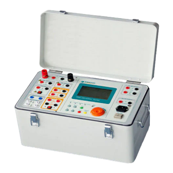
Page 8: Panel Introduction
T200A Hardware Operation Manual 2. Panel introduction High power output (I1): it’s mainly applied for CT test and primary side injection. High power output(U ): 10~300V, it’s mainly applied for DC act time testing and low voltage operation test to the tripping coil on intermedia/high voltage breaker. High power output (U1): it’s mainly applied for CT test and primary side injection. - Page 9 T200A Hardware Operation Manual operation temperature of the power module inside the equipment exceeds 80℃. Overload lamp: it will turn on the lamp and close the output when an overload of current and/or voltage occurs. Open-circuit lamp: it will flame if an open circuit is detected at the current output . Menu selection, parameter setting and adjustment’s output control areas.
-
Page 10: Technique Parameters
T200A Hardware Operation Manual 3. Technique parameters High power AC current output (I1) Range 0.5A~20A 10A~250A Accuracy ±0.5% Output voltage 130V~95V 10V~7.5V Power (±5%) 2000VA (20A) 2000VA(250A) Output current 250A 100A <50A Allowed output 120s 750s 3000s continuous time High power AC voltage output (U1) Range 10-500V Accuracy... - Page 11 T200A Hardware Operation Manual Auxiliary DC voltage output (Aux Udc) Range 20~240V Accuracy ±1% Power 55W at 110V/110W at 220V Load time continuous at 0.5A AC/DC current output (I2) Mode AC output DC output Range 0~20A 0~20A 0.2~0.5A 0.5-20A 0.2-0.5A 0.5~20A Accuracy 2.5mA ±0.5%...
- Page 12 T200A Hardware Operation Manual High precision AC/DC current output (I3) Mode AC output DC output Range 0~200mA 0~200mA Accuracy ±0.5% ±0.5% Power(200mA) Frequency 20~100Hz —— Ammeter & Voltmeter Type Ammeter Voltmeter Range 0~6A AC/DC 0~600V AC/DC Accuracy ±1% ±1% Binary inputs Number Input characteristics 30-250VDC, or dry contact...
- Page 13 T200A Hardware Operation Manual Power supply Nominal input voltage 220Vac or 110Vac Permissible tolerance -20%~+15% Nominal frequency 50/60Hz Permissible frequency 45~65Hz Others Operation temperature -5~+50°C Operation humidity 5~95%, non-condensing Storage temperature -25~+70°C Weight 23kg Dimension (W*H*D) 440*255*255mm PC connection Ground Socket 4 mm banana socket;...
-
Page 14: Operation Guide
T200A Hardware Operation Manual 4. Operation guide 4.1 How to select test item The tester has a test unit selection area on the right bottom of the equipment panel, where gets 4 buttons: F1, F2, F3 and the menu. Press the MENU button in the area, you will enter into the main menu directly. -
Page 15: How To Select Variable
T200A Hardware Operation Manual 4.2 How to select variable In the test item interface, rotate the ENTER button (clockwise or counter clockwise) to select the variable. The variable you selected will be displayed in white characters with black background. 4.3 How to set parameters When the variable was selected, press the ENTER button and rotate it clockwise or counter-clockwise to change the magnitude of the variable. -
Page 16: Report's View And Save
T200A Hardware Operation Manual 4.5 Report’s view and save 4.5.1 Report view Select the view option in the main menu to go into the report view interface, where you may view all saved reports. Here, each page can display 10 reports. With total 3 pages, it can save 30 reports at most. -
Page 17: System Setting
T200A Hardware Operation Manual 4.6 System setting Select the system setting option in the main menu, and then go to its interface, where you can set time, volt, freq., off delay. Time can be represented by second or cycles. Off delay:When the tester receive a trip or reclose signal from the relay under test, the tester will generate the voltage and current continually, until the delay time end. -
Page 18: Introduction To Test Function
T200A Hardware Operation Manual 5. Introduction to test function 5.1. Aux DC Mainly provide power supply for protection or relay Select the Aux DC menu as above figure shown. Set the output voltage value,press the Run button to output ... -
Page 19: Any Test
T200A Hardware Operation Manual 5.2. Any test 5.2.1 Manual &Meter This unit can output high power AC voltage/current, high power DC voltage, high precision voltage/current and display the reading values of voltmeter and ammeter. It can realize manual control on the amplitude, phase of AC variables or amplitude of DC variables by the step. - Page 20 T200A Hardware Operation Manual Shot Select output variables from the menu: AC-I1 -250A, AC-I1-20A, AC-U1, -2.5A, U -0.5A, AC/DC-I2, AC/DC-U2, AC/DC-I3 Set the start value and duration time of variables. Press the Run button to output. When the tester receives the binary input of ...
- Page 21 T200A Hardware Operation Manual AC-I3, DC-I3 Set variable, start value, stop value, step and step time. Press the Run button to start output, shown as figure. The variable will gradually increase on the step from the start value to the stop value. When the tester receives the binary input of protection acting signal and finish recording the action time, the test will stop.
-
Page 22: Relay Test
T200A Hardware Operation Manual 5.3 Relay test 5.3.1 Pick up test... - Page 23 T200A Hardware Operation Manual The output models are AC-I1, AC Test, AC-U1, DC Test, UDC-2.5A, AC-I3, UDC-0.5A, DC-I3 In AC Test and DC Test, the outputs are U2 and I2 with similar interface. Here we take AC Test as an example. For high power output, you can manually control the amplitude to change on the step.
-
Page 24: Trip Time Test, Trip Time + Pulse Length Test
T200A Hardware Operation Manual 5.3.2 Trip time test, Trip time + pulse length test The output models are: AC-I1, AC Test, AC-U1, DC Test, UDC-0.5A, AC-I3, DC-I3 In AC Test and DC Test, the outputs are U2 and I2 with similar interface. Here we take AC Test as an example. - Page 25 T200A Hardware Operation Manual There have two states for setting. You can set amplitude and phase for these two states, and the tester will count time when entering into the 2nd state. Perform tests on the action time in all kinds of over-voltage/current and ...
- Page 26 T200A Hardware Operation Manual 1. Wiring: 2. Test process Select item Udc-0.5A——Set parameter——Test starts...
-
Page 27: Reclosing
T200A Hardware Operation Manual 5.3.3 Reclosing This unit can perform reclosing test . There are two states for setting. You can set amplitude and phase for these two states. During test, you must connect the relay’s acting contacts and reclosing contacts ... -
Page 28: Under Freq Test
T200A Hardware Operation Manual 5.3.4 Under freq test You can set end frequency, df/dt, frequency setting. You can have a test on action value, action time, df/dt, under-voltage blocking value in under-cycle load-shedding device: Parameter setting Voltage amplitude: it should be larger than the voltage blocking value of ... - Page 29 T200A Hardware Operation Manual When the 5s end, the voltage and current frequencies will drop from 50Hz at df/dt to the end frequency. At the same time, the tester will start to count time when the frequency has dropped to the frequency setting: If the relay acts, while the action contacts are connected to the binary ...
-
Page 30: Differential Test
T200A Hardware Operation Manual 5.3.5 Differential test This function is designed to test differential relay with independent restraint coil and differential coil. The items, such as the trip value, time and differential current tripping value under different restraint current, can be tested. Test results can be recorded. Test process: 1) Action value: Select test item, and then go into the differential test unit;... - Page 31 T200A Hardware Operation Manual Press the Run button, the tester will start to output based on the settled I1, I2. When the tester receives the binary input of relay acting signal and finish recording the action time, the test will stop. Note: In Manual &...
-
Page 32: Harmonic
T200A Hardware Operation Manual 5.3.6 Harmonic This unit can have superposition of 2nd, 3rd, 5th,7th harmonics on the fundamental to execute the harmonic surge blocking test and harmonic overflux blocking test of transformers, Select test item, and then go into the harmonic restrained unit; Set parameters. -
Page 33: Synchronism Test
T200A Hardware Operation Manual 5.3.7 Synchronism test This function is for checking the performance of synchronism relay Condition: power supply frequency, 50Hz or 60Hz. Connect wires as above figure shown. Select the synchronizing test menu as above figure shown. ... -
Page 34: Directional Test
T200A Hardware Operation Manual 5.3.8 Directional test This function can be realized in the AC test of Pick Up. This unit can make the boundary for power direction relay. Connect wires as above figure shown. Select high precision AC test menu as above figure shown. ... -
Page 35: Dc Relay, Ma Level; Ac & Dc Test
T200A Hardware Operation Manual 5.3.9 DC relay, mA level; AC & DC test Connect wires as above figure. Select Relay test→Pick up→High precision DC-I3 test menu, shown as above figure. Set DC current value from the menu. Press the Run button to output DC current, adjust DC current, and record ... -
Page 36: Motor Overload Test
T200A Hardware Operation Manual 5.3.10 Motor overload test This unit can test trip time of motor. The output current values can be set in two states, the tester will count time when press the ENTER button. There are two ways to record the action time. Firstly, as soon as the tester ... -
Page 37: Ct Test
T200A Hardware Operation Manual 5.4 CT Test: 5.4.1 Primary side injection Connect wires as above figure, and connect the I1 output into the CT primary side Select high power AC current menu, shown as above figure. Select a appropriate current output range ... -
Page 38: Ratio Test
T200A Hardware Operation Manual 5.4.2 Ratio test Connect I1 output to the CT primary side and CT secondary side to the current measuring terminal, shown as above figure. Don’t make open circuit. Select the Ratio 250A menu, shown as above figure. ... -
Page 39: Polarity Test
T200A Hardware Operation Manual 5.4.3 Polarity test Employ the method of inputting the pulse voltage at CT primary side to have the CT polarity test. Connect wires as above figure shown. Please connect the polarity terminals of CT primary and secondary sides correctly. Press the function button, then the tester will output a voltage pulse. -
Page 40: Winding Resistance Test
T200A Hardware Operation Manual 5.4.4 Winding resistance test Connect wires as above figure shown Select the secondary DC Resistance test menu, shown as above figure. Set the DC current values for output, and environment temperature. Press the Run button to output the DC current, the tester will display the DC ... -
Page 41: Excitation Curve Test
T200A Hardware Operation Manual 5.4.5 Excitation curve test Connect wires as above figure shown Select the Excitation Curve test menu, shown as above figure. Set the start current value for output Press the Run button to output the start current, elevate the current gradually ... -
Page 42: Secondary Impedance Test
T200A Hardware Operation Manual 5.4.6 Secondary impedance test Connect wires as above figure shown. Disconnect the connecting sheet inside the CT terminal box heading to CT winding. Select the Manual&Meter menu, shown as above figure. Set the current value for output, which is normally the secondary current rating. ... -
Page 43: Dc Test Of Operating Loop
T200A Hardware Operation Manual 5.5 DC test of operating loop Connect wires as above figure shown. Select the Manual&Meter menu, shown as above figure. Select the DC voltage value from the menu. Press the Run button to output the DC voltage, adjust DC voltage value, and ... -
Page 44: Timer
T200A Hardware Operation Manual 5.6 Timer Single channel test Double channels test Connect wires as above figure shown Select the Timer menu, shown as above figure. Set single channel and/or double channels from the menu. Press the Run button to start the test. The action time will be measured ... -
Page 45: Voltage/Current Measuring Function
T200A Hardware Operation Manual 5.7 Voltage/current measuring function Select the Manual& Meter menu, shown as above figure. This unit could measure internal or external voltage and current, and when you measure DC resistance or secondary impedance and CT ratio/excitation curve, this measure part have to be in series with/ in parallel with the output variable(current or voltage), or take it as a measurement tool to measure external variable. -
Page 46: Pc Report Program
T200A Hardware Operation Manual 6. PC report program 6.1 Install the report program The program is working in platform of Windows XP, WINDOWS 7 or WINDOWS 10 at 32/64bits. Please do not connect T200A with PC during installation process. Double click the program to install. Select Next until the Driver installation notice is coming out as below picture. - Page 47 T200A Hardware Operation Manual process. Press OK to finish this process. Re-start the PC Connect T200A with PC via USB cable, and the driver will automatically identify and finish the installation.
-
Page 48: Run The Program
T200A Hardware Operation Manual 6.2 Run the program Double click the program icon. Click the PC Control on T200A software. In the report program, it will show the connection status as below. - Page 49 T200A Hardware Operation Manual The connection is not successful, please change the USB port or re-install the driver program.
- Page 50 T200A Hardware Operation Manual When the connection is done successfully, the function of Get report is enabled. There are two report formats generated: Word and TXT.
-
Page 51: Report Sample
T200A Hardware Operation Manual 6.3 Report sample Word format report:... - Page 52 T200A Hardware Operation Manual TXT format report...
-
Page 53: T200A Accessories
T200A Hardware Operation Manual 7. T200A Accessories This chapter describes the optional equipments and accessories for the T200A test set. Please visit the PONOVO Web site www.relaytest.com / www.ponovo.com.cn for up-to-date information. Standard accessories Item Part No. Color coded current cables... -
Page 54: Soft Bag For Test Leads
T200A Hardware Operation Manual 7.1 Soft Bag for Test Leads The T200A Wiring Accessory Package contains the following articles: Colour coded current cables SAW0001 colour coded current cable Amount: 2 pieces The current cables to connect the T200A output to other safety sockets of, generally the current parts, voltage and signal tripping. - Page 55 T200A Hardware Operation Manual Color coded voltage cables SAW0002 Colour coded voltage cable Amount: 8 pieces The voltage cables to connect the T200A output to other safety sockets of, generally the voltage parts, current and signal tripping. Signal Cable SAW0003 Signal cables Amount: 6 pieces It connects the T200A with other different sockets, generally with signal tripping and current/voltage testing.
- Page 56 T200A Hardware Operation Manual Short lead SAW0004 Short lead Amount: 4 pieces It is used for the series or parallel connect between the relay terminals. Crocodile Clips SAW0005 Crocodile clips 10mm SAW0006 Crocodile clips 20mm Amount: 8 pieces 4 pieces Crocodile clips for secondary side to connect to pins or screw types.
- Page 57 T200A Hardware Operation Manual U Clamps SAW0007 U clamps Amount: 2 pieces It is used to connect test leads with screw type terminals. ---------------------------------------------------------------------------------- Notes: One end of the adapters have no Users insert the non-safety into the insulator, users should make sure there is terminals and screw it firmly, then connect no output during connecting the adapters.
- Page 58 It is used to connect test leads with screw type terminals. Power Cord SAW0009 Power code Amount: 1 piece Power cord connects the T200A with power supply socket. PONOVO will provide relevant plug socket according to different countries. For the plug socket information, please check the Chapter 11. Appendix.
- Page 59 T200A Hardware Operation Manual Earthing Lead T200A SAW0018 Earthing lead Amount: 1 piece Earthing lead connects the T200A with ground to ensure kit safety. ------------------------------------------------------------------------------- Notes: In order to avoid static induction, ground reliably before testing. users should connect the T200A with -------------------------------------------------------------------------------...
- Page 60 T200A Hardware Operation Manual 10. Data cable (USB) SAW0011 Data cable (USB) Amount: 1 piece The data cable connects the T200A with PC for communications. - 60 -...
-
Page 61: Transportation Case
T200A Hardware Operation Manual 7.2 Transportation Case The large-size case with wheels is designed for heavy transport stress with folding hand it is made of fireproof materials and smooth rolling rubber tires. SAC0106 Transportation case - 61 -...
Need help?
Do you have a question about the T500 Series and is the answer not in the manual?
Questions and answers