Table of Contents
Advertisement
Quick Links
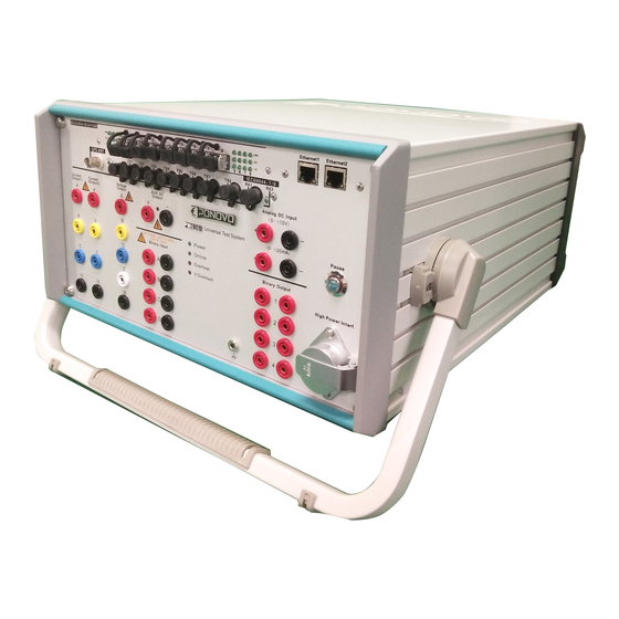
PW636i-F Hardware Instruction Manual
PONOVO POWER CO., LTD
No. 139 Jinghai Third Road, BDA, Beijing, China, 100176
Office
TEL. +86 (10) 59089666
E-Mail
Info@relaytest.com
Website
www.relaytest.com
HARDWARE INSTRUCTION MANUAL
VERSION:
DATE :
This manual is the publisher of PONOVO POWER CO., LTD. To make any kind of copy of this
manual please contact PONOVO POWER CO., LTD in advance.
This manual represents the technical status for the moment of publishing. The product information,
description and specifications mentioned in the manual do not have any contact binding force and
PONOVO POWER CO., LTD remains the right to make modifications to the technical
specifications and configurations without prior notice. PONOVO POWER does not take
responsibility to the possible error/mistakes in this manua
PW636I-F
PW636i-F-AE-1.50
JUNE 2020
1
Advertisement
Table of Contents

Related Manuals for Ponovo PW636I-F


Summary of Contents for Ponovo PW636I-F
- Page 1 DATE : JUNE 2020 This manual is the publisher of PONOVO POWER CO., LTD. To make any kind of copy of this manual please contact PONOVO POWER CO., LTD in advance. This manual represents the technical status for the moment of publishing. The product information, description and specifications mentioned in the manual do not have any contact binding force and PONOVO POWER CO., LTD remains the right to make modifications to the technical...
-
Page 2: Table Of Contents
PW636i-F Hardware Instruction Manual CONTENS 1. PREFACE................................. 4 2. SAFETY PRECAUTION ............................5 3. DESIGNED APPLICATIONS ..........................6 3.1 P ................................. 6 RODUCT FEATURES 4. OPERATION PREPARATION ..........................7 4.1 P ..................................7 REPARATION 4.2 C PC ................................7 ONNECTING 5. - Page 3 ..............................23 ENERAL DESCRIPTION 8.2 S ................................23 ADDRESS 8.2 S PC ........................23 TEPS FOR SETTING ADDRESS IN 9. PW636I-F-RELATED PRODUCTS AND ACCESSORIES ................ 26 9.1 PGPS02-GPS- ) ............... 27 BASED YNCHRONIZATION EVICE PTIONAL 9.2 PGPS04 -GPS- ) ..............27...
-
Page 4: Preface
PW636i-F Hardware Instruction Manual 1. Preface This manual gives detailed introduction to At the test site user should also refer to other PW636i-F so that user can have the safety and test regulations required by his reasonable, effective and safe operation of this management authorities. -
Page 5: Safety Precaution
PW636i-F Hardware Instruction Manual 2. Safety precaution In case the power outlet for powering up the PW636i-F dose not have protective ground customer must connect the ground socket of to the protective PW636i-F ground at the test site Please turn off the output before connecting/disconnecting the test object The voltage output of over 36V is considered as dangerous and care must be taken It’s not allowed to feed external voltage into the voltage/current output sockets... -
Page 6: Designed Applications
PW636i-F Hardware Instruction Manual 3. Designed applications Binary outputs PW636i-F can be used by power plants, 8 binary inputs in two groups, 4 of dry substations, and relay manufactures, etc, for contact type and 4 of semiconductor the following test applications. -
Page 7: Operation Preparation
PW636i-F Hardware Instruction Manual 4. Operation preparation 4.1 Preparation Be sure that the following preparation/system components are ready before operating the test equipment: PW636i-F test equipment Main supply cable (delivered) LAN control cable (delivered) PC with PowerTest software properly installed ... -
Page 8: General Description
PW636i-F Hardware Instruction Manual 5. General description 5.1 DSP card High performance DSP (digital signal processor) is used on the DSP card to ensure the accurate and fast signal generation. To get the satisfied accuracy and resolution the 32 bit D/A data converting technology is applied. -
Page 9: Ethernet Port
PW636i-F Hardware Instruction Manual 5.3 Ethernet port The Ethernet port is used to connect to external PC via Ethernet control cable. Please refer to “Getting ready for connecting to PC” for details... -
Page 10: Current Booster Interface
PW636i-F Hardware Instruction Manual 5.4 Current booster interface This interface is used to connect to the external current booster (optional) for testing high burden relays. Signal Current IA Current IN Current IB Current IN Current IC Current IN Current Ia... -
Page 11: Pause Button
PW636i-F Hardware Instruction Manual 5.5 Pause button The Pause button on the front panel is designed to cut the current/voltage outputs either for test purpose or under emergency case. ‘Manual’ control mode ‘Auto’ control mode Push ‘Pause’ button cut the current/voltage... -
Page 12: Fiber Optic
PW636i-F Hardware Instruction Manual 5.7 Ethernet Fiber optic There are 8 groups of fiber optic ports to support IEC61850-9-1/2, GOOSE and IEEE1588 Fiber socket: TX (Send), RX (Receive) Link indicator: if the fiber optic communicates well, the green indicator will light after power Rx/Tx indicator: it will light when there is data transferring. -
Page 13: Rear Panel
PW636i-F Hardware Instruction Manual 5.10 Rear panel Binary input group 2 IP reset button Binary output group 2 Main power supply External amplifier and low level output Power switch interface GPS interface(Only for Analog) -
Page 14: External Amplifier And Low Lever Output Interface
PW636i-F Hardware Instruction Manual 5.11 External amplifier and low lever output interface This interface is used to connect to external amplifier (optional) to increase the output channel and output power. Signal Low level output 1 Low level output 2 Low level output 3... -
Page 15: Gps Interface
PW636i-F Hardware Instruction Manual 5.12 GPS interface This interface is used to connect to our optional PGPS02 and PGPS04i GPS-based synchronization device (It is only for Analog). PGPS04i PGPS02 Signal Contact pin Power 1 only for PGPS02 Ready DB9 Chassis contact, male... -
Page 16: Ip Reset
PW636i-F Hardware Instruction Manual 5.13 IP reset This reset button is used to restore the IP address of to the default factory setting. PW636i-F Press this button Switching on the power for PW636i-F After this operation the IP address will be restored to the following settings. -
Page 17: Hardware Configuration
PW636i-F Hardware Instruction Manual 6. Hardware configuration 6.1 Current generators configuration Basic QuickTest (4V,6I) PW636i-F has 6 current generators in two State sequence (4V, 6I) groups. They can be configured as either 3 Protection Differential(6I) Advanced Advanced Differential(6I) currents mode or 6 current mode. -
Page 18: Current In Series Connection In 3 Current Mode
PW636i-F Hardware Instruction Manual 6.3 Current in series 6.4 Voltage generators connection in 3 current mode PW636i-F has 4 voltage generators. In 3 current mode the two current generators can be connected in series to increase the compliance voltage. Example: IA and IB are connected in series... -
Page 19: Connect Two Voltage Generators In Series
PW636i-F Hardware Instruction Manual 6.5 Connect two voltage generators in series We can connect two voltage generators in series to get higher voltage output range. Example: VA and VB are connected in series ---------------------------------------------- Note: The maximum voltage output will... -
Page 20: Binary Input And Output
PW636i-F Hardware Instruction Manual 7. Binary input and output 7.1 General description 7.2 Binary Input The device has 8 binary inputs. Electricity is PW636i-F has 12 binary inputs in two groups. isolated in A-H. Space contact or active There are 8 in the panels and other 4 connecting from the kit. -
Page 21: Polarity Of Binary Inputs
PW636i-F Hardware Instruction Manual 7.3 Polarity of binary 7.5 Isolation of the inputs Binary Inputs The polarity reference of the binary inputs are shown All 8 binary inputs are galvanically isolated bellow from each other. 7.4 Binary configuration The software interface for binary configuration (A-H) shows below. -
Page 22: Binary Outputs
PW636i-F Hardware Instruction Manual 7.7 Binary outputs These 4 binary outputs are high speed semiconductor type. PW636i-F has 8 binary outputs in two groups 7.8 Fiber optic The binary outputs 1-4 are placed on the front panel. There are 8 paris of fiber optic interface used for SMV and GOOSE and IEC61588 communications. -
Page 23: Getting Ready For Pc Controlled Operation
2~254 (except 133 and 153). Steps for setting IP address for computer. PowerTest test software must be properly installed on the PC to control PW636i-F. The Step 1: Left click ‘Start/Control panel/Network installation description of PowerTest test connection’... - Page 24 PW636i-F Hardware Instruction Manual Step 2: Right click ‘Local connection’ icon Step 4: Click the ‘Properties’ button Step 3: Left click the ‘Properties’ ---------------------------------------------- Note: the last section of IP address can be any number between 2-254 (except 133 and...
- Page 25 PW636i-F Hardware Instruction Manual Step 7: Check if IP is set properly If IP address is properly set we will see on the right bottom corner the following display If we see the following display on the right bottom corner then we need to make the...
-
Page 26: Pw636I-F-Related Products And Accessories
PW636i-F Hardware Instruction Manual 9. PW636i-F Related Products and Accessories This chapter describes the optional equipments and accessories for the PW636i-F test set. Please visit the PONOVO Web site www.relaytest.com for up-to-date information. Notes: All the pictures are for reference only. -
Page 27: Pgps02-Gps-Based Synchronization Device (Optional)
SAG0101 PGPS02 You can synchronize two or more PONOVO test sets by connecting a PGPS SAG0201 PGPS04i synchronization unit to each of the test sets’ For detailed information about the PGPS, inputs. -
Page 28: Pss01 Circuit Breaker Simulator (Optional)
PW636i-F Hardware Instruction Manual 9.3 PSS01 Circuit 9.4 Phpc01 Current Breaker Simulator Booster (Optional) (Optional) Phpc01 current booster is designed to supply high compliance voltage even at small current t can simulate circuit breaker behaviors in range, suitable for testing high burden three pole or 1 pole tripping of 6-500KV electromagnetic current relays. -
Page 29: Pacb108 Scanning Head (Optional)
PW636i-F Hardware Instruction Manual 9.5 PACB108 Scanning 9.6 Low Level Output and Head (Optional) Counter Input Cable The passive optical scanning head PACB108 (Optional) detects the status of an LED, that is either an optical pulse output from an energy meter or the binary status of a protective relay or other similar optical source. -
Page 30: Standard Accessories
The PW636i-F Wiring Accessory Package contains the following articles: 1. Colour coded current cables 8 pieces 4 pieces Amount: The current cables to connect the PW636i-F output to other safety sockets of, generally the current parts, voltage and signal tripping. - Page 31 PW636i-F Hardware Instruction Manual 2. Color coded voltage cables Amount: 5 pieces The voltage cables to connect the PW636i-F output to other safety sockets of, generally the voltage parts, current and signal tripping. 3. Signal Cable Amount: 8 pieces 8 pieces It connects the PW636i-F with other different sockets, generally with signal tripping and current/voltage testing.
- Page 32 PW636i-F Hardware Instruction Manual 4. Flexible Terminal Adapter Amount: 20 pieces Flexible terminal adapter connect to screw-clip terminals. -------------------------------------------------------------------------------------- Notes: One end of the adapters have no Users insert the non-safety into the insulator, users should make sure there is terminals and screw it firmly, then connect no output during connecting the adapters.
- Page 33 PW636i-F Hardware Instruction Manual 5. Jumper Cable Amount: 4 pieces Flexible jumper connects current outputs in parallel. 6. Crocodile Clips Amount: 8 pieces Crocodile clips for secondary side to connect to pins or screw types.
- Page 34 PW636i-F Hardware Instruction Manual 7. U Clamps U clamps 1# U clamps 2# Amount: 20 pieces 10 pieces U clamps for screws to connect regular test leads to screw-clamp terminals relays. ------------------------------------------------------------------------------------------ Notes: One end of the adapters have no...
- Page 35 PW636i-F Hardware Instruction Manual 8. Pin clamps Amount: 8 pieces Pin clamps for screws to connect regular test leads to screw-clamp terminals relays. 9. Banana plug adapter Amount: 12 pieces Banana plug adapter for screws to connect regular test leads to UK terminals.
- Page 36 D03 Power code QP3D Power code Amount: 1 piece Power cord connects the PW636i-F with power supply socket. PONOVO will provide relevant plug socket according to different countries. ----------------------------------------------------------------------------------------- NOTE: D03: Adapter is mainly used in German, Finland, France, Norway, Sweden, Poland, South Korean, Austria, Spain, Hungary, Czech, Ukraine, Turkey, Brazil and Russia etc.
- Page 37 Amount: 1 piece Earthing lead connects the PW636i-F with ground to ensure kit safety. ------------------------------------------------------------------------------------------ Notes: In order to avoid static induction, users should connect the PW636i-F with ground reliably before testing. ------------------------------------------------------------------------------------------ 13. PC control cable (LAN) Amount: 1 piece...
-
Page 38: Transportation Case
PW636i-F Hardware Instruction Manual 9.7.2 Transportation Case The large-size case with wheels is designed for heavy transport stress with folding hand it is made of fireproof materials and smooth rolling rubber tires. -
Page 39: Troubleshooting
PW636i-F Hardware Instruction Manual 10. Troubleshooting 1. Power Indicator doesn’t work. 1). Check if there is electricity in power supply. 2). Check if the input fuse is blown. If the fuse is broken, check if the input power is correct and change the fuse. - Page 40 PW636i-F Hardware Instruction Manual Turn off antivirus software, and then test again. Sometiems computer system may affect online result, please change computers. Please note if the kit IP address has been changed. Press “IP reset” button to switch on kit and confirm the IP in “IP Set”.
- Page 41 PW636i-F Hardware Instruction Manual or voltage short-circuit alarm while high voltage output. 7. Output waveform is incorrect. Check the setting output value. Check if the open circuit casue no oscillogram. Check if the parameter setting of output monitor windows is correct, each amplitude is too big, and the phase color is the same as grounding.
- Page 42 PW636i-F Hardware Instruction Manual When the frequency is not accurate, check if the current and voltage’s output frequncy in general unit are correct first. If the frequency differential is beyond the range, please check as following method: 1) Check if the site instrument works well.
- Page 43 PW636i-F Hardware Instruction Manual The three-phase current power of kit can be used by parallel connection. Users need set the phase output. It is suggested to set amplitude the same. The total output amplitude of phase parallel connection is: I=Ia+Ib+Ic=30 + 30 + 30= 90A 14....
Need help?
Do you have a question about the PW636I-F and is the answer not in the manual?
Questions and answers