
Related Manuals for iDule ID25MGB-CL


Summary of Contents for iDule ID25MGB-CL
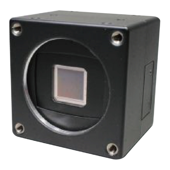
- Page 1 25M CMOS Camera ID25MGB-CL (B/W) ID25MGC-CL (COLOR) Technical Manual iDule Corporation...
-
Page 2: Table Of Contents
Table of Contents PAGE Product Outline ............................3 Handling Precautions ........................... 3 Specification ..............................4 3.1. General Specification ............................. 4 3.2. Camera Output Signal Specification ......................... 5 3.3. Spectral Response (Representative Value) ....................... 6 Connector ..............................7 4.1.Camera Link Connector 12226-1100-00PL (3M) ....................7 4.2. -
Page 3: Product Outline
Product Outline ID25MGB-CL/ID25MGC-CL is a Camera Link interfaced and 25M resolution camera module. 25M pixels CMOS sensor with diagonal length 18.130mm is utilized. Entire pixels can be read out within 1/22.6s at Full Configuration output. Features Global Shutter CMOS sensor is utilized. -
Page 4: Specification
Specification 3.1. General Specification (1) Image Sensor Device type Diagonal length 18.130mm, Global Shutter type (GPIXEL GMAX0505) Effective pixel number 5136(H) x 5120(V) 2.5(H) x 2.5(V) μm Unit cell size Φ18.130mm Image circle 12.800 12.840 (単位:mm) (2) Video Output Frequency 79.75MHz Pixel Clock 5.6fps... -
Page 5: Camera Output Signal Specification
3.2. Camera Output Signal Specification Effective Video Output 5136(H) x 5120(V) Video Output Data LVAL Camera Link (LVDS) Sync Signal Output FVAL DVAL (Exposure output) FVAL 12pin Connector 6pin (LVTTL) Exposure 12pin Connector 10pin (LVTTL) CC2・CC3・CC4 Camera Link (LVDS) (No Function) Camera Control Signal Input (4)Trigger Input... -
Page 6: Spectral Response (Representative Value)
3.3. Spectral Response (Representative Value) -
Page 7: Connector
Connector 4.1.Camera Link Connector 12226-1100-00PL (3M) (Power LED) (CN1) (P2) (P1) Connector (P2) Connector (P1) Name Name Name Name +12V(PoCL) +12V(PoCL) Yclk- Yclk+ Xclk- Xclk+ 100Ω Terminated SerTC+ SerTC- SerTFG- SerTFG+ CC1- (Trigger IN -) CC1+ (Trigger IN +) CC2+ CC2- Zclk- Zclk+... -
Page 8: Power Led
4.2. Power LED LED lights when the camera is operational. If the power is not supplied or the camera is broken, the LED will not light. ※ LED can be turned off (address 1Bh) by serial setting. 4.3. 12pin Connector HR10A-10R-12PB (HIROSE) (CN1) IO(5V LVTTL) +5.0V(VCC) Name... -
Page 9: Timing Chart
Timing Chart 5.1. Horizontal Synchronous Signals Timing (2Tap Base Configuration : 5.6fps ) Image Out Camera Link Port A 5128 5130 5132 5134 ・ ・ ・ ・ ・ ・ ・ ・ ・ ・ ・ ・ ・ ・ ・ ・ ・ ・ ・ Camera Link Port B 5129 5131 5133 5135 ・ ・ ・ ・ ・ ・ ・ LVAL Out DVAL Out 160 CLK Effective Data : 2568 CLK 1H : 2728 CLK Camera Link ... -
Page 10: Horizontal Synchronous Signals Timing (3Tap Base Configuration : 7.5Fps )
5.3. Horizontal Synchronous Signals Timing (3Tap Base Configuration : 7.5fps ) Image Out Camera Link Port A 5127 5130 5133 ・ ・ ・ ・ ・ ・ ・ ・ ・ ・ ・ ・ ・ ・ ・ ・ ・ ・ ・ Camera Link Port B 5128 5131 5134 ・ ・ ・ ・ ・ ・ ・ ・ ・ ・ ・ ・ ・ ・ ・ ・ ・ ・ ・ Camera Link Port C 5129 5132 5135 ・ ・ ・ ・ ・ ・ ・ LVAL Out DVAL Out 334 CLK Effective Data : 1712 CLK... -
Page 11: Horizontal Synchronous Signals Timing (4Tap Medium Configuration : 11.3Fps)
5.5. Horizontal Synchronous Signals Timing (4Tap Medium Configuration : 11.3fps) Image Out Camera Link Port A 5128 5132 ・ ・ ・ ・ ・ ・ ・ ・ ・ ・ ・ ・ ・ ・ ・ ・ ・ ・ ・ Camera Link Port B 5129 5133 ・ ・ ・ ・ ・ ・ ・ 5130 5134 Camera Link Port C ・ ・ ・ ・ ・ ・ ・ 5131 5135 Camera Link Port D ・ ・ ・ ・ ・ ・ ・... -
Page 12: Horizontal Synchronous Signals Timing (8Tap Full Configuration : 22.6Fps )
5.7. Horizontal Synchronous Signals Timing (8Tap Full Configuration : 22.6fps ) Image Out Camera Link Port A 5128 ・ ・ ・ ・ ・ ・ ・ ・ ・ ・ ・ ・ ・ ・ ・ ・ ・ ・ ・ Camera Link Port B 5129 ・ ・ ・ ・ ・ ・ ・ Camera Link Port C 5130 ・ ・ ・ ・ ・ ・ ・ Camera Link Port D 5131 ・ ・ ・ ・ ・ ・ ・ Camera Link Port E 5132 ・ ・ ・ ・ ・ ・ ・... -
Page 13: Output Format
5.9. Output format (1) B&W 5136(H) ・・・ 5128 5129 5130 5131 5132 5133 5134 5135 8Tap Full 出力 4pixel 4pixel 4Tap Medium 出力 3pixel 3ap Base 出力 2pixel 2pixel 2ap Base 出力 (2) Color 5136(H) 5128 5129 5130 5131 5132 5133 5134 5135... -
Page 14: Fixed Trigger Shutter Mode
5.10. Fixed Trigger Shutter Mode This is the mode to start exposure with external input trigger signals, and set the exposure time with serial □ commands. Delay time (Exposure Time Delay) from detecting trigger edge in the camera to starting exposure. □... -
Page 15: Pulse Width Trigger Shutter Mode
5.11. Pulse Width Trigger Shutter Mode This is the mode to start exposure with external input trigger signals, and set the exposure time with □ pulse width of the trigger signals. □ Delay time (Exposure Time Delay) from detecting trigger edge in the camera to starting exposure, and from detecting trigger end edge to completing exposure. -
Page 16: Partial Scan Mode
Partial Scan Mode □ 1 partial area can be set by serial commands. Function Address(Hex) Data(Hex) Full frame scan mode (00h) Partial scan mode ON/OFF Partial scan mode (01h) min:0(0000h) ~ max:5119(13FFh) Partial scan mono 40-41 min:0(0000h) ~ max:5118(13FEh) Start position color Partial scan mono... - Page 17 □ Total number of frames = Number of V blanking lines (fixed to 64H) + Number of partially valid lines (Partial scan start position + number of partial valid lines) <= 5120 must be satisfied. Partial scan start position and number of partial effective lines □...
- Page 18 Horizontal cutout function It is possible to cut out the left and right in the horizontal direction with 24 pixels x n. The frame rate does not change even if you cut out the horizontal direction. Function Address(Hex) Data(Hex) min:0(00h) ~ max:106(6Ah) L/R Cut size(pixel) = setting value x 24pixel Horizontal cut-out min:0= Full...
-
Page 19: Remote Communication
Remote Communication Via camera link cable, the camera can be controlled. Communication Settings :115200bps (fixed) Baud Rate Data :8bit Stop bit :1bit Parity :None :No Control XON / XOFF ・ Send Command Format (Host to Camera) If send a command, set the command and parameter between STX and ETX. command parameter (ASCII code) (02H) -
Page 20: Command Specifications
8.1. Command Specifications 1) Set some values of resister 【Command】 Set : Resister ・・・ Data (Variable-length:max 16 address) Address 【Return Value】 Succeed ・・・ Fail ・・・ 2) Get some value of resister 【Command】 Get : Resister Address Number of data acquisition (optional) 【Return value】... - Page 21 3) Set User’s data 【Command】 Set : User’s data ・・・ Table No. User’s data (fixed length :16byte) (0~3) 【Return Value】 Succeed ・・・ Fail ・・・ 【Remarks】 The commands, sets free data on the specified register, and can use 4 tables (1 table : 16 characters). 4) Get User’s data 【Command】...
- Page 22 5) Save all configurations 【Command】 Configuration : Save 【Return Value】 Succeed ・・・ Fail ・・・ 6) Restore all configurations 【Command】 Configuration : Restore 【Return Value】 Succeed ・・・ Fail ・・・ 7) Get a model name 【Command】 Query : Model name 【Return Value】 Succeed ・・・...
- Page 23 9) Get a firmware version 【Command】 Query : Version 【Return Value】 Succeed ・・・ ・・・ Version information (fixed length:8byte) Fail ・・・ 10) Get a detail of error information 【Command】 Query : Error 【Return Value】 Succeed ・・・ Kind Detal Fail ・・・ Kind Detail 0:...
-
Page 24: Control Example
8.2. Control Example 1) How to check trigger shutter mode. ( The command gets a value from address 04) 【Send Command】 Address 04 【Return value form camera】 Data 01 【Receive Return Value】 The camera is working with a trigger shutter mode, because the command received a 01 from the camera. 2) How to check trigger shutter mode. - Page 25 How to set partial scan mode. (The command sets 01 for address 08) 【Send Command】 Address 08 Data 01 【Return value form camera】 【Receive Return Value】 The command finished normally, because the command received ACK from the camera. How to set 01FF for manual shutter. (The command set 01FF for address 24) 【Send Command】...
- Page 26 How to save configurations of a camera. (The command send CS) 【Send Command】 【Return value form camera】 【Receive Return Value】 The command finished normally, because the command received ACK from the camera. How to restore the camera to initial settings. (The command send CR) 【Send Command】...
- Page 27 How to get detail of a communication error. 【Send Command】 Set the address invalid value 【Return value form camera】 【Receive return value】 The command finished abnormally, because the command received ‘NAK’ from the camera. When the command did not finish normally, retry to send command or send to get detail of a detail error command. 【Send Command】...
-
Page 28: Function Setting
Function Setting Function Address(Hex) Data(Hex) 2Tap Base 3Tap Base 4Tap Medium 8Tap Full 00: 1/6s 1/8s 1/12s 1/23s 01: 1/9s 1/10s 1/15s 1/30s 02: 1/12s 1/15s 1/25s 1/50s 03: 1/25s 1/30s 1/50s 1/100s 04: 1/50s 1/60s 1/100s 1/200s 05: 1/100s 1/150s 1/200s 1/400s... - Page 29 Function Address(Hex) Data(Hex) 00: 8Tap Full Configuration 01: 4Tap Medium Configuration Camera output mode 02: 2ap Base Configuration 03: 3ap Base Configuration 00: 8bit 8Tap, 4Tap, 3Tap, 2Tap Configuration Output bit 01: 10bit 8Tap, 4Tap, 2Tap Configuration 12bit 4Tap, 2Tap Configuration min:0(00h) ~ max:106(6Ah) L/R Cut size(pixel) = setting value x 24pixel LL:...
- Page 30 Function Data(Hex) Address(Hex) Manual white balance R min:0(0h) ~ max:767(02FFh) 28-29 (color) x1.0(0dB) ~ x4.0(+12dB) Gain = (setting value+256) / 256 Manual white balance B 0(0000H) : x1.0(0dB) 2A-2B LLHH: (color) 256(0100H) : x2.0(+6dB) Manual white balance G 767(02FFH) : x4.0(+12dB) 2C-2D (color) min:0(0000h) ~ max:5119(0FFFh)
-
Page 31: Dimensions
Dimensions 4-M3 4(対面同様) 4-M3 2-M3 4(対面同様) Cマウント... -
Page 32: Initial Setting
10. Initial Setting Function Address Data Preset shutter 00: OFF(1/22.6s) Preset white balance 3200K (Color) 00: Trigger shutter mode Normal (Trigger OFF) 00: Trigger polarity Positive 00: Trigger input 00: Partial scan Full frame scan mode Output mode 00: 8Tap Full Configuration 00:... -
Page 33: Cases For Indemnity (Limited Warranty)
On very rare occasions, however, CMOS pixel defects might be noted with time of usage of the products. Cause of the CMOS pixel defects is the characteristic phenomenon of CMOS itself and IDULE is exempted from taking any responsibilities for them. Should you have any questions on CMOS pixel defects compensation, please contact us.
Need help?
Do you have a question about the ID25MGB-CL and is the answer not in the manual?
Questions and answers