
Related Manuals for Haulotte HA 41 PX


Summary of Contents for Haulotte HA 41 PX
- Page 1 OPERATING AND MAINTENANCE INSTRUCTIONS SELF-PROPELLED LIFT HA 41 PX 242 032 9720 - E 07.06...
- Page 3 Main tool free 1-877-HAULOTTE Fax / Fax + 44 (0) 1952 292758 Service tool free 1-877-HAULOT-S Haulotte Singapore Pte Ltd Haulotte Netherlands BV Tél / Phone + 65 6536 3989 Tél / Phone + 31 162 670 707 Fax / Fax...
- Page 5 The person who would have intervened for any operation of this kind will take responsibility and recall in question the EEC marking validity granted by Haulotte. The EEC declaration will become null and void and Haulotte will disclaim regulation responsibility.
- Page 6 • The Haulotte warranty • Haulotte technicians’ and repair agents’ technical support 5. AVAILABILITY Using Haulotte original spare-parts allows you to take advantage of 40 000 references available in our permanent stock and a 98% service rate. WHY NOT TAKE ADVANTAGE ?
- Page 7 Operating and maintenance instructions GENERAL You have just taken delivery of your HAULOTTE self-propelled platform. It will give you complete satisfaction if you follow the operating and maintenance instructions exactly. The purpose of this instruction manual is to help you in this.
- Page 8 Operating and maintenance instructions...
-
Page 9: Table Of Contents
Operation and Maintenance CONTENTS GENERAL RECOMMENDATIONS - SAFETY ............1 1.1 - GENERAL WARNING ....................1 1.1.1 - Manual ............................. 1 1.1.2 - Labels ............................1 1.1.3 - Safety............................1 1.2 - GENERAL SAFETY INSTRUCTIONS................. 2 1.2.1 - Operators ..........................2 1.2.2 - Environment.......................... - Page 10 Operation and Maintenance 2.5 - OBSTRUCTIONS.......................11 2.5.1 - Obstruction characteristics ..................... 11 2.6 - LABELS........................12 2.6.1 - "Yellow" Labels........................12 2.6.2 - "Orange" labels ........................12 2.6.3 - "Red" labels ........................... 13 2.6.4 - Other labels ..........................14 2.6.5 - Optional biodegradable oil...................... 14 2.6.6 - Optional 240V plug.........................
- Page 11 Operation and Maintenance USE ..........................23 4.1 - SAFETY MEASURES....................23 4.1.1 - Displacement (controlled from the platform panel) ..............23 4.1.2 - Filling the fuel tank ......................... 23 4.2 - UNLOADING - LOADING - DISPLACEMENT - PRECAUTIONS......24 4.2.1 - Unloading with ramps ......................24 4.2.2 - Loading ..........................
- Page 12 Operation and Maintenance SAFETY SYSTEM ......................55 7.1 - TURRET CABINET RELAY AND FUSE FUNCTIONS ..........55 7.2 - SAFETY CONTACT FUNCTIONS ................55 ELECTRICAL DIAGRAMME..................57 8.1 - FOLIO 01/06 ......................57 8.2 - FOLIO 02/06 ......................58 8.3 - FOLIO 03/06 ......................59 8.4 - FOLIO 04/06 ......................60 8.5 - FOLIO 05/06 ......................61...
-
Page 13: General Recommendations - Safety
GENERAL WARNING 1.1.1 - Manual This manual is designed to familiarise the operator with HAULOTTE self- propelled platforms in order to ensure efficient and safe use. However, it cannot replace the basic training required by any user of site equipment. -
Page 14: General Safety Instructions
Caution ! Only trained operators can use There must always be at least two operators present, so that one of them Haulotte self-propelled platforms. at ground level can: • Take fast action if necessary. • Take over the controls in case of accident or malfunction. - Page 15 Operating and maintenance instructions To reduce the risks of serious falls, operators must respect the following instructions: • Hold the guardrail firmly when moving the platform. • Remove any traces of oil or grease from the platform steps, floor or guardrails.
-
Page 16: Residual Risks
Operating and maintenance instructions 1.3 - RESIDUAL RISKS 1.3.1 - Risks of jerky movements and tipping over Caution ! The direction of travel can be Risks of jerky movement and instability are high in the following situations: reversed after a 180° turntable - Sudden action on the controls. -
Page 17: Inspections
Operating and maintenance instructions 1.4 - INSPECTIONS Comply with the national regulations in force in the country of machine use. NOTE : For AUSTRALIA: .refer to AS2550.10. For FRANCE: Order dated 1st March 2004 + circular DRT 93 dated 22 September 1993 which specify: 1.4.1 - Periodic inspections The machine must be inspected every 6 months in order to detect any... -
Page 18: Repairs And Adjustments
PINGUELY-HAULOTTE unauthorised. The manufacturer cannot be held responsible if non-original parts are used or if the work specified above is not performed by PINGUELY-HAULOTTE- approved personnel. 1.6 - CHECKS BEFORE RETURNING UNIT INTO SERVICE To be performed after: •... -
Page 19: Presentation
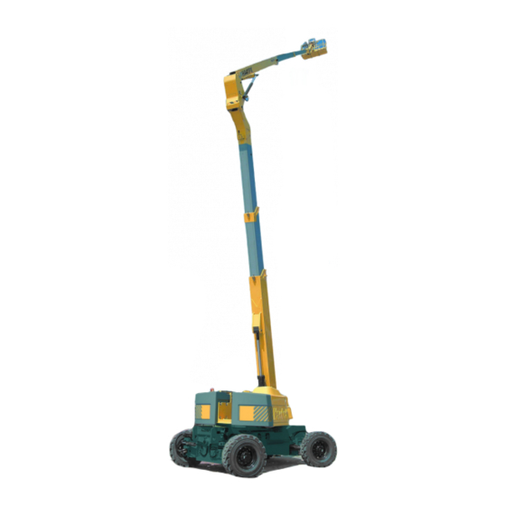
Operation and Maintenance PRESENTATION The model HA 41PX motorised platforms is designed for all work at heights within the limit of their characteristics (see chap. 2.3, page 9, and chap. 2.4, page 10) and respecting all the security instructions specific to the materials and the places of use. -
Page 20: Principal Components
Operation and Maintenance 2.2 - PRINCIPAL COMPONENTS 1 - Rolling frame 13 - Part of connection arm/beam 2 - Driving wheels and forward steering 14 - Hydraulic motors for transfers + reduction gear 15 - Right Compartment (hydraulic reservoirs and diesel, 3 - Driving wheels and rear steering control panel) 4 - Suspension platform... -
Page 21: Working Area
Operation and Maintenance 2.3 - WORKING AREA ft in -13ft 1in 13ft 1in 26ft 2in 39ft 4in 52ft 5in 65ft 7in 137ft 9in 131ft 2in 124ft 8in 118ft 1in 111ft 6in 104ft 11in 98ft 5in 91ft 10in 85ft 3in 78ft 8in 72ft 2in 65ft 7in 59ft... -
Page 22: Technical Characteristics
Operation and Maintenance 2.4 - TECHNICAL CHARACTERISTICS 2.4.1 - Design features DESIGNATIONS HA41PX Overall length 12,60 m 41 ft 4 in Overall width 2,53 m 8 ft 3 in Overall height 2,99 m 9 ft 9 in Ground clearance 0,38 m 1 ft 2 in Height in transport position 3,70 m... -
Page 23: Obstructions
8 ft 3 in 2,99 m 9 ft 9 in 3,5 m 11 ft 48 in 0,294 m 0,96 ft F X G 2,44 m X 0,8 m 8 ft X2 ft 62 in 3,7 m 12 ft 1 in HA41PX HAULOTTE... -
Page 24: Labels
Operation and Maintenance 2.6 - LABELS 2.6.1 - "Yellow" Labels 2.6.2 - "Orange" labels... -
Page 25: Red" Labels
Operation and Maintenance 2.6.3 - "Red" labels Composant spÈcifique ‡ cette machine. NE PAS INTERCHANGER. Component specific to this machine. DO NOT INTERCHANGE. Komponenten nur f¸r diese maschine geeignet. BITTE AUF EINE ANDERE MASCHINE NIGHT MONTIEREN. N∞ MACHINE - MASCHINE N∞ 7814 518... -
Page 26: Other Labels
Operation and Maintenance 2.6.4 - Other labels 7814-393 7814-394 2.6.5 - Optional biodegradable oil... -
Page 27: Optional 240V Plug
3078143620 Risk of crushing (hands and fingers) 3078150770 Disengagement 3078143520 Hydraulic oil 3078148890 Biodegradable oil (optional) 307P217080 Haulotte 3078151420 Do not wait in the working area 3078143600 Do not wash... do not use machine... 307P217060 Turret lectern 3078144650 Tilt 307P218080... -
Page 28: Positioning Of The Labels
Operation and Maintenance 2.6.8 - Positioning of the labels... -
Page 29: Operating Principles
Operation and Maintenance OPERATING PRINCIPLES 3.1 - HYDRAULIC SYSTEM All the movements of the machine are ensured by the hydraulic power provided by a power pack. 3.1.1 - Lateral movement 3.1.1.1 -Lateral (displacement of the machine) The lateral movement is fed by a hydraulic pump with closed loop, variable flow and electric drive. -
Page 30: Platform Compensation
In order to purge the circuit following maintenance or to compensate for a forbid the use of the machine until micro-leakage which may create a shift/slip, the machine is equipped with this is repaired by Haulotte After a device to facilitate the re-levelling of the linkage. Sales Service. -
Page 31: Control Of The Platform Load
Operation and Maintenance Caution ! 3.2.3 - Control of the platform load In the event of a malfunction of the safety measures, only specialised If the platform load exceeds the maximum authorised load, no movement personnel may carry out the is not possible from the platform control unit. -
Page 32: Defects
HA41PX HAULOTTE jib. It is active only when the arm is lowered, the fly jib retracted and raised less than 5°. The platform must be empty of personnel and material when this command is carried out. -
Page 33: Head Calculator
After Sales Service, or when a technician or Haulotte agent service it, we will not be able to apply the manufacturer's guarantee for the calculator nor for the machine. - Page 34 Operation and Maintenance...
-
Page 35: Use
Operation and Maintenance 4.1 - SAFETY MEASURES To prevent use of the machine over and above its limits, safety measures are provided in order to protect personnel and the machine. WHEN THE MACHINE IS DEPLOYED, IT MUST ALWAYS REMAIN ON POWER SO THAT THE SAFETY SYSTEMS ARE ACTIVE. -
Page 36: Unloading - Loading - Displacement - Precautions
Operation and Maintenance • Do not draw from a barrel if this has not been decanted and never use fuel at its bottom. Because of fire hazard during the filling of the tank, take the following precautions: • do not smoke •... - Page 37 Operation and Maintenance • the anchoring points provided for this purpose must be used • the turret must be blocked with the pin. To climb the ramps of a truck, select low movement speed. Pmax Pmax 16,5 T 6,6 T 36.376 lb 14.551 lb 3,8 m...
-
Page 38: Operations Before First Use
Operation and Maintenance 4.3 - OPERATIONS BEFORE FIRST USE IMPORTANT: before each use of the machine or after a period of storage, it is necessary to refer to the start-up operations of (chap. 5.3, page 42) in order to check the various levels, and to check various machine maintenance points. -
Page 39: Familiarisation With The Control Units
Operation and Maintenance 4.3.1 - Familiarisation with the control units 4.3.1.1 -Turret lectern/control panel Photo 1 Turret control panel 1- Electrical pre-heating indicator 12- Platform compensation /transport position 2 - Oil pressure indicator 13 - Emergency stop button 3 - Engine temperature indicator 14 - Electrical pre-heating 4 - Battery load meter 15 - Turret/axle/platform control panel selector... - Page 40 Operation and Maintenance 4.3.1.2 -Platform control panel NOTE : When you wish to move, it is important to raise the suspension platform a few meters in order to prevent the platform touching the ground during displacement Photo 2 Platform control panel 1 - Arm or fly jib position selector 12 - Movement control, forward axle direction 2 - Arm lifting, fly jib raising and turret turning control...
-
Page 41: Controls Before Use
Operation and Maintenance 4.3.2 - Controls before use 4.3.2.1 -Evolution Zone • make sure that the machine is resting on flat ground which is stable and able to support the weight of the machine (see chap. 2.4, page 10 - pressure on the ground). NOTE : See table of characteristics in chap. -
Page 42: Bringing Into Service
Operation and Maintenance Photo 4 Photo 5 Caution ! When refilling, use products • Check the clogging indicators of the hydraulic oil filters. If the red tes- recommended in the ingredients ter is visible, replace the filter cartridge (see chap. 5.3.2, page 43) and chapter (chap. -
Page 43: Operations Starting From Ground
Operation and Maintenance Caution ! 4.4.1 - Operations starting from ground In normal use the turret control panel is a rescue station or breakdown service and should be 4.4.1.1 -Motor Ignition: Photo 1‚ page 27 used only when absolutely • Make sure that the emergency stop keys are pulled out necessary. - Page 44 Operation and Maintenance Caution ! If the two chock jacks are extended, Photo 7 the axle extension controls are temporarily disabled. Caution ! Make sure that the platform cannot Axles extension: touch the ground when the front • Start the machine, switch the control panel position selector key (con- axles are raised (lever rep.
- Page 45 - Check that the extension of the telescope stops in accordance with Photo 9, page 33. - If telescope continues to extend, immediately shut off the telescopic extension control. The system must be repaired by Haulotte maintenance personnel before the machine may be used.
-
Page 46: Operations Starting From The Platform
Operation and Maintenance 4.4.1.5 -Main movement controls • test the movement by raising the fly jib in the direction it is mounted then lowering it (control rep. 9, Photo 1, page 27). • stop the descent of the fly jib when it is in the horizontal position •... - Page 47 Operation and Maintenance Test the directional movement of the front axle using the selector placed on the handle of the movement control (contr rep. 12, Photo 2, page 28), ), and test that of the rear axle by using the selector located on the platform control panel (control rep.
-
Page 48: Emergency Descent
Operation and Maintenance 4.5 - EMERGENCY DESCENT Photo 10 There may be cases where the operator in the platform is no longer able to control its movement, even through the machine is functioning normally. An able-bodied operator on the ground can use the "turret" lectern with main diesel power source to retrieve the operator on the platform. -
Page 49: Disengagement
Operation and Maintenance 4.6.2 - Disengagement Operating mode: Caution ! It is prefereable to carry out this • Remove the transmission panel (rep. 1, Photo 11) by unscrewing the operation on a flat and horizontal 2 holding screws (rep. 2, Photo 11). area of ground. - Page 50 Operation and Maintenance...
-
Page 51: Maintenance
Certain operations must be carried out more frequently and particular precautions must be taken: consult the engine manufacturer's notice and your local HAULOTTE agent on this subject. Only competent HAULOTTE trained personnel should work on the machine and these should follow safety requirements for the protection of Personnel and the Environment. -
Page 52: Maintenance Plan
• The symbol represents the tool to be used (or the operation to be car- ried out). 5.2.1 - Consumer items Lubricants used by ITEM SPECIFICATION SYMBOL TOTAL PINGUELY HAULOTTE SHELL Engine oil SAE 15W40 RIMULAX SHELL TRANSELF SPIRAXA Gearbox oil SAE 80W-90... -
Page 53: Maintenance Diagramme
Operation and Maintenance 5.2.2 - Maintenance diagramme Hours 1 000 2 000 1 000 2 000... -
Page 54: Operations
Operation and Maintenance 5.3 - OPERATIONS 5.3.1 - Summary table FREQUENCY OPERATIONS NUM- BERS Daily or before each • Check the levels of the: - engine oil - coolant - hydraulic oil - fuel - electric batteries • Check the cleanliness of the: - fuel pre-filter - engine air filter - machine (specifically check the water-tightness of the connections... -
Page 55: Operating Mode
Operation and Maintenance Every 500 hours or • Engine: see manufacturer's notice every 6 months • Drain the wheel reduction gear. Refill: 4 x 1,4l capacity. • Check the play between crown wheel and reduction gear teeth (this should be between 0.3 and 0.6 mm) •... - Page 56 Operation and Maintenance Caution ! Before dismantling, ensure that the oil circuit is not pressurised and that the oil is not too hot. 5.3.2.2 -Powered wheel reduction gear Photo 16 Wheel reduction gear • Checking the level: - Rotate the wheel so that you place 1 stopper (1) on a horizontal line and 1 stopper (2) on a vertical line.
- Page 57 After carrying out any work on any part of the hydraulic circuit of the machine, a static test should always be carried out before returning the machine into service. The tasks below must be carried out by trained competent personnel: contact Haulotte Services. Caution ! The service operation of a machine...
- Page 58 Operation and Maintenance Fig. 4 - Configuration 1 Configuration 1 (Fig. 4, page 46) : • With the arm gently raised, the fly jib raised to its cutoff point, with the fly jib telescopic arm extended. • oMeasure side X1 between the underside of the arm and the turret reinforcement (Photo 18).
-
Page 59: List Of Consumer Items
/or fly jib raised compen- sation If one of the values measured is higher than the maximum acceptable value, contact Haulotte Services for repair of the affected jack(s) before returning the machine to service.. 5.3.3 - List of consumer items •... - Page 60 Operation and Maintenance Caution ! In order to safeguard the elevating This chain shall not assist in stabilising the platform prior ti it reaching a platform against tipping during the point of tipping should it occur for any reason i.e. uncontrolled application stability test, it is imperative that a of test load.
-
Page 61: Operating Incidents
6, page 51 to see if these are reported. In this case, you simply need to follow the instructions.If not, you should contact your HAULOTTE agent or the After Sales Service of the manufacturer. Before diagnosing the breakdown, you should check that: •... - Page 62 Operation and Maintenance INCIDENTS PROBABLE CAUSE SOLUTIONS The engine Error indicator flashes in 4 • Break in one of the fly jib te- • Evacuate the user from the stops flash sequences lescopic arm chains machine and call in After Sales Service Error indicator The engine...
- Page 63 Operation and Maintenance INCIDENTS PROBABLE CAUSE SOLUTIONS No platform Reach limit indicator lights • The movement requested is • Return to the base position movement when a movement is re- not permitted in this context (retract the telescopic arms, quested lower the fly jib or arms) so that the the movement will be permitted again...
- Page 64 Operation and Maintenance INCIDENTS PROBABLE CAUSE SOLUTIONS No platform The error indicator flashes • Failure of one or more fuses • Replace the defective fuse. movement in 6 flash sequences (FU7, 8, 5, 6 or 2) If the problem persists, call in After Sales Service Error indicator Impossibility...
- Page 65 Operation and Maintenance INCIDENTS PROBABLE CAUSE SOLUTIONS While running Ditto + reach limit indicator • Ditto, but more serious • Evacuate the user from the an arm com- machine and call in After mand, the en- Sales Service gine stops and will not restart.
- Page 66 Operation and Maintenance INCIDENTS PROBABLE CAUSE SOLUTIONS No axle retrac- Alarm • The machine is not in the ri- • Switch the selector key to tion/extension ght configuration the turret position, fold the machine completely, align the turret along the axis Alarm is set off •...
-
Page 67: Safety System
Operation and Maintenance SAFETY SYSTEM 7.1 - TURRET CABINET RELAY AND FUSE FUNCTIONS (see chap. 8, page 57) FU1-10A Engine power supply fuse FU2-3A "Chassis" position movement fuse FU3-80A Pre-heating fuse FU4-30A Weak power control fuse, calculators FU5-3A "Turret" position movement fuse FU6-3A "Platform"... - Page 68 Operation and Maintenance SQ35 ILS receivers - rear jacking retracted SQ36/37 ILS switches - axle track extended SQ38/39 ILS switches - axle track retracted SQ40 Turret chassis axis alignment position switch SQ41 Fuel reserve position switch SQ42 Turret chassis axis alignment position switch SQ43 ILS detector - telescopic fly jib arms SQ44/45...
-
Page 69: Electrical Diagramme
Operation and Maintenance ELECTRICAL DIAGRAMME 8.1 - FOLIO 01/06 S hunt... -
Page 70: Folio 02/06
Operation and Maintenance 8.2 - FOLIO 02/06... -
Page 71: Folio 03/06
Operation and Maintenance 8.3 - FOLIO 03/06... -
Page 72: Folio 04/06
Operation and Maintenance 8.4 - FOLIO 04/06... -
Page 73: Folio 05/06
Operation and Maintenance 8.5 - FOLIO 05/06 S hunt... -
Page 74: Folio 06/06
Operation and Maintenance 8.6 - FOLIO 06/06... -
Page 75: Nomenclature
Operation and Maintenance 8.7 - NOMENCLATURE FOLIO-COL DESIGNATION 05 - 14 Weight relative angle gauge 05 - 14 Weight absolute angle gauge 03 -20 Engine overheat manifold 03 -19 Engine low oil pressure manifold 03 -18 Hydraulic oil overheat manifold 01 -17 Optional hydraulic oil overheating cooler thermostat 06 -13... - Page 76 Operation and Maintenance FOLIO-COL DESIGNATION 01 - 3 Ignition 01 -16 Emergency pump 02 -18 Hour meter 01 - 7 Preheating Resistor 02 - 2 Power-on selector 02 - 7 Position selector key 03 -13 Accelerator switch 05 -13 Differential jacking switch 05 -15 Platform rotation switch 05 -20...
- Page 77 Operation and Maintenance FOLIO-COL DESIGNATION SQ42 04 - 8 Turret right-angle redundant position receiver SQ43 04 - 9 Fly jib telescopic arm ILS detector SQ44/45 04 - 10 Telescopic arm ILS detector 02/03/04/05/06 HEAD calculator 05 - 15 Weighing card 01 - 11 Fuel pump 01 - 9...
- Page 78 Operation and Maintenance...
-
Page 79: Hydraulic Diagramme
Operation and Maintenance HYDRAULIC DIAGRAMME 9.1 - SHEET 1/3... -
Page 80: Sheet2/3
Operation and Maintenance 9.2 - SHEET2/3... - Page 81 Operation and Maintenance 9.3 - SHEET 3/3...
-
Page 82: Nomenclature
Operation and Maintenance 9.4 - NOMENCLATURE NUMBER DESIGNATION SCHEMA SHEET No N° LATERAL MOVEMENT PUMP EQUIPMENT PUMP EMERGENCY GROUPE LATERAL MOVEMENT HYDRAULIC MOTOR DIRECTION REDUCTION MOTOR PLATFORM ROTATION JACK EQUIPMENT DISTRIBUTOR PLATFORM FUNCTIONS HYDRAULIC BLOCK LATERAL MOVEMENT DRIVING BLOCK LATERAL MOVEMENT BLOCK 2 DIVIDERS LATERAL MOVEMENT BLOCK 1 DIVIDERS ELECTRONIC PARALLEL DISTRIBUTOR BRAKE RELEASE CONTROL BLOCK...
Need help?
Do you have a question about the HA 41 PX and is the answer not in the manual?
Questions and answers