Sign In
Upload
Download
Table of Contents
Contents
Add to my manuals
Delete from my manuals
Share
URL of this page:
HTML Link:
Bookmark this page
Add
Manual will be automatically added to "My Manuals"
Print this page
×
Bookmark added
×
Added to my manuals
Manuals
Brands
ADC Manuals
Network Hardware
HRE-204 List 1
User manual
ADC HRE-204 List 1 User Manual
Remote enclosure
Hide thumbs
1
2
3
4
Table Of Contents
5
6
7
8
9
10
11
12
13
14
15
16
17
18
19
20
21
22
23
24
25
26
27
28
29
page
of
29
Go
/
29
Contents
Table of Contents
Bookmarks
Table of Contents
Table of Contents
Overview
Features
Applications
Backplane
Figure 1. HRE-204 List 1 and List 2 Backplane
Figure 2. Backplane Slot Connections
Table 1. Backplane Connectors
Slot Connectors
Installation
Installation Kit
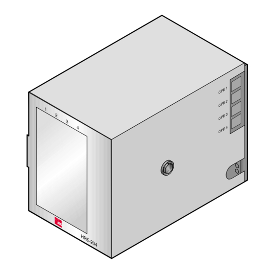
Figure 3. HRE-204 List 1 and List 2 Remote Enclosure
Mounting Options
Desktop Mounting
Wall Mounting
Figure 4. Side Panel Assembly
Figure 5. HRE-204 List 1 and List 2 List 1 Backplate
Figure 6. Wall Mounting and Hinging View
Optional Hinged Wall Mounting
Figure 7. Optional Mounting Hinge
Turn-Up
Power and Grounding
Volt Power Options
Figure 8. TB3 and TB4 Pin Assignments
Table 2. Power Requirements for Various Plug Applications
Pin Assignments
Slot Pin Assignments
Figure 9. HRU Pin Assignments (All Lists)
Figure 10. HLU-431 Pin Assignments
Figure 11. ERU-412 Pin Assignments
HLU Alarm Output Interface
Facility Side HDSL Connections
Figure 12. System Alarm (TB5) Pin Assignments
Figure 13. TB1 Pin Assignments
Figure 14. TB2 Pin Assignments
CPE DS1 (G.703) Connections
Figure 15. RJ48C Pin Assignments (List 1)
Figure 16. RJ48X Pin Assignments (List 2)
Appendix A - Specifications
Appendixb - Abbreviations
Appendix C - Product Support
Bar Code and Configuration Number Information
Figure 17. Bar Code and Configuration Number Label Locations
Table 3. Bar Code and Configuration Number Label Descriptions
Certification and Warranty
Advertisement
Quick Links
Download this manual
HiGain
HiGain
U
M
SER
ANUAL
HRE-204 List 1 and List 2
HiGain Remote Enclosure
Product Catalog: 150-204-100-03
CLEI: T1MF5004, T1MF6004
Table of
Contents
Previous
Page
Next
Page
1
2
3
4
5
Advertisement
Table of Contents
Need help?
Do you have a question about the HRE-204 List 1 and is the answer not in the manual?
Ask a question
Questions and answers
Related Manuals for ADC HRE-204 List 1
Network Hardware ADC HRM-238 L1 User Manual
Higain retrofit management shelf (26 pages)
Network Hardware ADC HiGain HRE-420 User Manual
(22 pages)
Network Hardware ADC HiGain HRU-402 Manual
(52 pages)
Network Hardware ADC HRE-602 List 1 User Manual
(22 pages)
Network Hardware ADC HRE-425 List 1 User Manual
(28 pages)
Network Hardware ADC HRE-425 List 1 Quick Installation
Line unit (9 pages)
Network Hardware ADC HRE-204 List 2 User Manual
Remote enclosure (29 pages)
Network Hardware ADC HiGain H2TU-C-388 User Manual
Adc h2tu-c-388 list 1 line unit user manual (66 pages)
Network Hardware ADC H4TU-C-319 List 1 Line Unit User Manual
Central office (co) side of a t1 transmission system (79 pages)
Network Hardware ADC HiGain H2TU-C-319 List 4E User Manual
Adc higain h2tu-c-319 list 4e line unit user manual (88 pages)
Network Hardware ADC HiGain HMS-317 List 2 Quick Installation Manual
(32 pages)
Network Hardware ADC HiGain HLU-388 List 5 Quick Installation
Line unit (7 pages)
Network Hardware ADC HiGain HLU-231 List 8F Quick Installation
Line unit (7 pages)
Network Hardware ADC HiGain HLU-432 User Manual
Line unit (74 pages)
Network Hardware ADC HIGAIN H2TU-R-402 LIST 7G Quick Installation
Remote unit (8 pages)
Network Hardware ADC HIGAIN H2TU-R-402-L7A1 Quick Installation
Remote unit (7 pages)
This manual is also suitable for:
Hre-204 list 2
150-204-100-03
Table of Contents
Print
Rename the bookmark
Delete bookmark?
Delete from my manuals?
Login
Sign In
OR
Sign in with Facebook
Sign in with Google
Upload manual
Upload from disk
Upload from URL


Need help?
Do you have a question about the HRE-204 List 1 and is the answer not in the manual?
Questions and answers