
Related Manuals for ADC HRE-425 List 1


Summary of Contents for ADC HRE-425 List 1
- Page 1 ANUAL H R E 4 2 5 H0333-A HRE-425 List 1 Remote Enclosure Product Catalog: 150-1114-01 CLEI: T1MFF504...
- Page 2 Contents herein are current as of the date of publication. ADC reserves the right to change the contents without prior notice. In no event shall ADC be liable for any damages resulting from loss of data, loss of use, or loss of profits, and ADC further disclaims any and all liability for indirect, incidental, special, consequential or other similar damages.
- Page 3 Unpack each container and inspect the contents for signs of damage. If the equipment has been damaged in transit, immediately report the extent of damage to the transportation company and to ADC DSL Systems, Inc. Order replacement equipment, if necessary.
- Page 4 150-425-100-04 September 22, 1999 HRE-425 List 1...
-
Page 5: Table Of Contents
Field Side HDSL Connections ..................11 CPE DS1 (G.703) Connections ..................13 Turn-Up............................15 Specifications________________________________________________________________________ 16 Product Support _____________________________________________________________________ 17 Bar Code and Configuration Number Information ________________________________________ 18 Abbreviations _______________________________________________________________________ 19 Certification and Warranty______________________________________________ Inside Back Cover HRE-425 List 1 September 22, 1999... - Page 6 3. Wall Mounting and Hinging View ......................... 5 4. HRE-425 List 1 Backplane..........................6 5. HRU Pin Assignments............................ 7 6. HRE-425 List 1 Shelf Fusing, Backplane Wiring and Bus Connections ............8 7. HDU-451 and EDU-451 Pin Assignments..................... 9 8. HLU-431 Pin Assignments .......................... 10 9.
-
Page 7: Overview
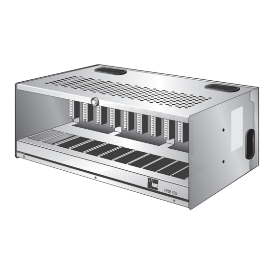
The HiGain Remote Enclosure HRE-425 List 1 houses HiGain line units, doubler units, and remote units (HLUs, HDUs, and HRUs, respectively). The HRE-425 List 1 can also accommodate a -48 Vdc power supply to power the slots, if required. Access to the twelve slots is provided by wire-wrap card-edge connectors or by four 25-pair, type 57, backplane connectors. -
Page 8: Applications
HiGain provides a quick and cost-effective way of delivering T1 High Capacity Digital Service (HCDS) to customers over metallic cable pairs. The primary application of the HRE-425 List 1 Remote Enclosure is to house the remote units of a HiGain repeaterless T1 transmission system. -
Page 9: Installation
150-425-100-04 NSTALLATION This section provides information on installing and mounting the HRE-425 List 1. NSTALLATION The installation kit contains the following items: • four rack mounting screws • four bracket attaching screws with locking nuts • four plastic cable tie wraps •... -
Page 10: Mounting Options
Locking bolt H0328-A Figure 2. HRE-425 List 1 Backplate Using the backplate as a template, mark the wall locations for drilling the wall-mounting holes. Drill pilot holes and attach the backplate to the backboard with the four No. 10 x inch PHS wood screws and washers supplied with the remote enclosure. -
Page 11: Rack Mounting
Attach the rack mounting brackets to the bracket mounting holes (see Figure 3) on each side panel with the four bracket attaching screws and locking nuts. Attach the HRE-425 to the rack with the four mounting screws included. HRE-425 List 1 September 22, 1999... -
Page 12: Backplane
4. These locations are numbered with their corresponding slot number, either below or above the rectangle. ADC recommends that pin 4 of TB1, frame ground, be connected to earth ground according to the grounding recommendations found in Section 9 of Bellcore’s GR-1089-DEC, 1996 (see Figure 6 on page 8). -
Page 13: Fuse Alarm
All the fuse alarm contacts are transmitted together on one bus and connected to the Fuse Alarm, pin 3 of TB1. If a fuse opens, the normally floating Fuse Alarm in pin 3 drives to -48 V. HRE-425 List 1 September 22, 1999... - Page 14 Power Source Fuse Frame -48Vdc Alarm Earth Ground 0.5A/2A 0.5A 0.5A SLOT 12 Optional Internal -48 Vdc Power Supply 120 Vac Power H0331-A Figure 6. HRE-425 List 1 Shelf Fusing, Backplane Wiring and Bus Connections September 22, 1999 HRE-425 List 1...
-
Page 15: Slot-Pin Assignments
HDSL2 INTIP 1 RS-232 DATA OUT RS-232 DATA IN FOR FACTORYTESTING DS1 RING1 HDSL1 RING HDSL1TIP DS1TIP1 CHASSIS GROUND Note: Active pins are highlighted in black. H0337-A Figure 7. HDU-451 and EDU-451 Pin Assignments HRE-425 List 1 September 22, 1999... - Page 16 RS-232 DATA OUT ALARM FUSE ALARM FACTORY BURN-IN (DO NOT USE) CIRCUIT GND DS1 RING1 HDSL1 RING HDSL1TIP DS1TIP1 CHASSIS GROUND Note: Active pins are highlighted in black H0338-A Figure 8. HLU-431 Pin Assignments September 22, 1999 HRE-425 List 1...
-
Page 17: Field Side Hdsl Connections
CHREV message is displayed in the ALARMS display field when viewing the HiGain Status screen. This condition does not affect system operation, but should be corrected to avoid any confusion regarding the identities of the two HDSL loops. HRE-425 List 1 September 22, 1999... - Page 18 P4 Pin No. Slot Pin No. HDSL 2 HDSL 2 Loop 2 In Loop 2 In (Doubler) (Doubler) Ring 1 Tip 1 (a) P3 Pins 13 through 25 and 38 through 50 are unused. September 22, 1999 HRE-425 List 1...
-
Page 19: Cpe Ds1 (G.703) Connections
P1 Pin No. Slot Pin No. (DS1, G.703) RX/OUT (DS1, G.703) RX/OUT Loop 1 Out Loop 1 Out (Doubler) (Doubler) Ring 1 Tip 1 (a) P1Pins 13 through 25 and 38 through 50 are unused. HRE-425 List 1 September 22, 1999... - Page 20 150-425-100-04 You can purchase optional 12-port RJ48 harmonic cable assemblies for the CPE interface from ADC: (refer to “Product Support” on page 17). • RJ48C (Part Number 150-2201-01), shown in Figure 10 on page 14 • RJ48X (Part Number 150-2201-02), shown in...
-
Page 21: Turn-Up
Open the front panel by loosening the Hex nut shown in Figure 1 on page 1, then gently lower the panel. Insert the card in the assigned slots. Refer to the card’s technical practice for the appropriate turn-up procedure. HRE-425 List 1 September 22, 1999... -
Page 22: Specifications
11.5 in. (30 cm.) Weight 22 lb. (9.9 kg.) The power supply capacity and its fuse must conform to the power required by the plugs being used. Consult the appropriate practice for each plug’s power requirements. September 22, 1999 HRE-425 List 1... -
Page 23: Product Support
UPPORT ADC Customer Service Group provides expert pre-sales and post-sales support and training for all its products. Technical support is available 24 hours a day, 7 days a week by contacting the ADC Technical Assistance Center. • Quotation Proposals Sales Assistance •... -
Page 24: Bar Code And Configuration Number Information
Configuration number label CLEI/ECI Bar code label H0342-A Side View Figure 12. HRE-425 List 1 Bar Code and Configuration Number Label Locations Table 3. HRE-425 List 1 Bar Code and Configuration Number Label Descriptions Item Description CLEI/ECI Bar code label Contains human-readable Common Language Equipment Identifier (CLEI) code number and Equipment Catalog Item (ECI) bar code number. -
Page 25: Abbreviations
Digital Signal, level 1 Equipment Catalog Item HCDS High Capacity Digital Service HDSL High-bit-rate Digital Subscriber Line HiGain Doubler Unit HiGain Line Unit HiGain Remote Enclosure HiGain Remote Unit Network Interface Device Return Material Authorization Receive Transmit HRE-425 List 1 September 22, 1999... - Page 26 150-425-100-04 September 22, 1999 HRE-425 List 1...
-
Page 27: Certification And Warranty
ADC may use reconditioned parts for such repair or replacement. This warranty does not apply to any product which has been repaired, worked upon, or altered by persons not authorized by ADC or in ADC's sole judgment has subjected to misuse, accident, fire or other casualty, or operation beyond its design range. - Page 28 ADC DSL Systems, Inc. 14402 Franklin Avenue Tustin, CA 92780-7013 Tel: 714.832.9922 Fax: 714.832.9924 Technical Assistance Tel: 800.638.0031 Tel: 714.730.3222 Fax: 714.730.2400 : 150-425-100-04 OCUMENT ´,Of¶5®¨ 1247705...
Need help?
Do you have a question about the HRE-425 List 1 and is the answer not in the manual?
Questions and answers