
Related Manuals for ADC H4TU-C-319 List 1 Line Unit


Summary of Contents for ADC H4TU-C-319 List 1 Line Unit
- Page 1 HDSL4 HDSL4 ANUAL H4TU-C-319 List 1 Line Unit Product Catalog: H4TU-C-319-L1 CLEI: VACJNUNE...
- Page 2 Contents herein are current as of the date of publication. ADC reserves the right to change the contents without prior notice. In no event shall ADC be liable for any damages resulting from loss of data, loss of use, or loss of profits, and ADC further disclaims any and all liability for indirect, incidental, special, consequential or other similar damages.
-
Page 3: Using This Manual
Unpack each container and inspect the contents for signs of damage. If the equipment has been damaged in transit, immediately report the extent of damage to the transportation company and to ADC DSL Systems, Inc. Order replacement equipment, if necessary. - Page 4 Inspecting Shipment LTPH-UM-1031-03, Issue 3 September 12, 2003 H4TU-C-319 List 1...
-
Page 5: Table Of Contents
LTPH-UM-1031-03, Issue 3 ABLE OF ONTENTS Overview ____________________________________________________________________________ 1 Features ...1 Applications ...2 Front Panel __________________________________________________________________________ 3 Installation___________________________________________________________________________ 8 Verification ...9 Verification without a Downstream Device ...9 Verification with a Downstream Device ...9 Provisioning_________________________________________________________________________ 10 Using the MODE and SEL Pushbuttons ...10 Setting Options through MODE and SEL ...10 Resetting to Factory Default...11 Displaying System Parameter Settings...11... - Page 6 Table of Contents System Alarms... 42 Alarm Option for DLC Feed... 44 Retiring System Alarms ... 44 Remote LOS and AIS Response ... 45 OCT55 Test Pattern with AMI Line Code ... 45 Loopback Operation ... 46 Generic Loopback Commands... 47 Special Loopback Commands...
- Page 7 5. Inventory Screen...16 6. Config Menu...17 7. Config Menu - Standard Options (defaults shown)...18 8. Config Menu - ADC Options (defaults shown) ...18 9. Config Menu - Set Factory Defaults ...23 10. Config Menu - Master Clear...24 11. System Spans...25 12.
- Page 8 3. Navigational Keys for the Maintenance Terminal Screens ... 12 4. Logon Screen Menus ... 13 5. H4TU-C-319 List 1 Standard Config Menu Options ... 19 6. H4TU-C-319 List 1 ADC Config Menu Options ... 20 7. DS1/DSX-1 24-Hour PM Threshold ... 22 8. Monitor Screen Descriptions ... 26 9.
-
Page 9: H4Tu-C-319 List
LTPH-UM-1031-03, Issue 3 VERVIEW The H4TU-C-319 List 1 is the Central Office (CO) side of a T1 transmission system. The ADC product family (hereafter referred to as “HDSL4”) is based on the HDSL4 standard ANSI T1.418 Issue 2. The H4TU-C, when used with an H4TU-R remote unit, transmits a 1.544 Mbps payload up to a maximum distance of 12 kft. -
Page 10: Applications
Overview • Both doubler and non-doubler applications are compatible with ADSL services in same binder group • Configuration options — Selectable DSX-1 pre-equalizer — Bipolar Violation Transparency (BPVT) — Bit Error Rate (BER) alarm — Power Back Off Network (PBON) and Power Back Off Customer (PBOC) options for configuring HDSL4 transmit power levels —... -
Page 11: H4Tu-C-319 List 1 Front Panel
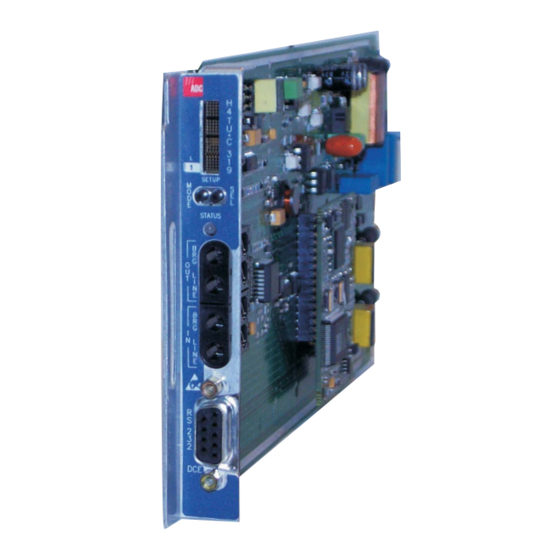
LTPH-UM-1031-03, Issue 3 RONT ANEL Figure 1 shows the H4TU-C-319 List 1 front panel. a list of front-panel display messages, refer to connector and craft port, refer to Card handle (CLEI and ECI bar code label on outside of handle) H4TU-C-319 List 1 Table 1 on page 4 Table 2 on page... -
Page 12: Front-Panel Description
Front Panel Front-Panel Feature Function Front-panel display Displays four-character status, provisioning, and alarm system messages. The front-panel display illuminates when power is initially applied. To conserve power the display only remains on for 5 minutes. Using the MODE or SEL pushbuttons reactivates the display and restarts the 5-minute timer. -
Page 13: Front-Panel Display Messages
LTPH-UM-1031-03, Issue 3 Table 2 lists the front-panel display messages. The four-character display reports the code of an alarm, loopback, or diagnostic message and, in some cases, is followed by a second four-character message that modifies the first message with a value or current configuration setting. Message Full Name ALARM MESSAGES... - Page 14 Front Panel Table 2. Front-Panel Display Messages (Continued) Message Full Name LOOPBACK MESSAGES CDU1 Customer Doubler 1 Loopback CDU2 Customer Doubler 2 Loopback CLOC Customer Local Loopback COLB Central Office Loopback CREM Customer Remote Loopback NDU1 Network Doubler 1 Loopback NDU2 Network Doubler 2 Loopback NLOC...
- Page 15 LTPH-UM-1031-03, Issue 3 Table 2. Front-Panel Display Messages (Continued) Message Full Name FRM xxxx Frame: SF, ESF, UNFR CODE xxxx Line Code: AMI, B8ZS LATT xx Loop Attenuation MARG xx Margin (a) System information messages scroll in the order listed. To scroll through the messages, press the MODE pushbutton for 3 or more seconds.
-
Page 16: Installation
Upon receipt of the equipment, inspect the contents for signs of damage. If the equipment has been damaged in transit, immediately report the extent of damage to the transportation company and to ADC. H4TU-C-319 Figure 2. Installing the H4TU-C-319 List 1 into a Shelf When installing an H4TU-C in a chassis, be sure to wear an antistatic wrist strap. -
Page 17: Verification
LTPH-UM-1031-03, Issue 3 ERIFICATION Once the H4TU-C is installed, verify that it is operating properly. To do this, monitor the following: • Status LED • Status messages reported by the front-panel display (see Verification without a Downstream Device If there is no downstream device installed: Verify that the H4TU-C powers up. -
Page 18: Provisioning
Provisioning ROVISIONING There are two methods for provisioning: • Use the MODE and SEL pushbuttons on the front panel of the H4TU-C to: — Set system options — Reset the H4TU-C to its factory default settings for system options — Display system option settings (scroll mode) —... -
Page 19: Resetting To Factory Default
LTPH-UM-1031-03, Issue 3 Resetting to Factory Default All user options for the H4TU-C-319 List 1 MODE and SEL pushbuttons. To set the user options to their default values: Press the SEL pushbutton for 6 seconds until the following message appears: DFLT NO Press the SEL pushbutton while the DFLT NO message is displayed. -
Page 20: Using A Maintenance Terminal
Provisioning SING A AINTENANCE Connecting to a Maintenance Terminal The craft port on the front panel allows you to connect the H4TU-C-319 to a maintenance terminal (ASCII terminal or PC running a terminal emulation program). Once connected to a maintenance terminal, you can access the maintenance, provisioning, and performance screens. -
Page 21: Logon Screen
Identifies the 100 most recent system events and reports the date and time of occurrence. Provides standard configuration options, ADC options, BER tester (BERT), date and time setting, and a reset option (factory settings). Also provides a master clear option that clears all performance, alarm, and event log entries. - Page 22 Provides a glossary of terms used in the maintenance screens, a list of navigational keys, print guide, and ADC contact information. September 12, 2003 LTPH-UM-1031-03, Issue 3 H4TU-C-319 List 1...
-
Page 23: Provisioning Tasks
“Setting Circuit ID Numbers” on page “Configuring the System” on page 24). Config Inventory Report +----------------------+ | Standard Options -> | ADC Options -> | BERT Generator -> Date and Time -> +-------------------------------+ | Date (mm/dd/yyyy): 02/01/2002| | Time (hh:mm[:ss]): 12:30:01... -
Page 24: Setting Circuit Id Numbers
Provisioning Setting Circuit ID Numbers The Inventory screen provides product information on all units in the system and allows setting of the circuit and unit identification numbers. Monitor Performance Event Log -------------------------- Unit : H4TU-C Product : H4TU-C-319 List Sw Ver : 4.00 Build # : 08... -
Page 25: Configuring The System
HDSL4 units when connected to units from other vendors. ADC options are an extended set of options available only when using ADC units exclusively. For a description of each option and a list of possible option settings, refer to... -
Page 26: Config Menu - Standard Options (Defaults Shown)
Figure 7. Config Menu - Standard Options (defaults shown) Monitor Performance Event Log Use <Spacebar> to cycle through option settings and <Enter> to activate ID: xxxx—-xxxx—-xxxx--xxxx Figure 8. Config Menu - ADC Options (defaults shown) Config Inventory Report +----------------------+ Standard Options ->... -
Page 27: H4Tu-C-319 List 1 Standard Config Menu Options
Table 5 describes the Standard Config menu options and lists their menu screen display codes. describes the ADC Config menu options. Selections in bold type are the factory default settings. Table 5. H4TU-C-319 List 1 Standard Config Menu Options Standard Config... -
Page 28: H4Tu-C-319 List 1 Adc Config Menu Options
(PBON and PBOC) Options” on page Power Back Off - PBOC Customer “Power Back Off (PBON and PBOC) Options” on page Table 6. H4TU-C-319 List 1 ADC Config Menu Options ADC Config Menu Screen Selection Options Display Code Line Power Feed PWRF... - Page 29 DS1 service (AMI or B8ZS) being provided by the system. The Auto mode, which can adapt to either AMI or B8ZS, should only be used in applications that require it (such as when ADC system acts as a standby circuit to DS1 circuits whose line codes are not known or may be both AMI and B8ZS).
-
Page 30: Ds1/Dsx-1 24-Hour Pm Threshold
Provisioning Alarm Pattern (ALMP) Option. To improve HDSL4 compatibility with the switch-to-protect features used in Digital Loop Carrier (DLC) feeder applications, the H4TU-C-319 has an ALMP option that allows you to select either an AIS or LOS DS1 output payload for the following alarms: •... -
Page 31: Config Menu - Set Factory Defaults
Figure 9. Config Menu - Set Factory Defaults H4TU-C-319 List 1 ENTER to cancel this action. Config Inventory Report +----------------------+ | Standard Options -> | ADC Options -> | BERT Generator -> | Date and Time -> | Master Clear Set Factory Defaults +----------------------+... -
Page 32: Clearing The History, Alarm, And Event Log Screens
ENTER to activate. Press to confirm (clear all screens). Config Inventory Report +----------------------+ | Standard Options -> | ADC Options -> | BERT Generator -> | Date and Time -> Master Clear | Set Factory Defaults | +----------------------+ 02/01/2002 12:30:01 H4TU-C Figure 10. -
Page 33: Monitoring System Activity And Performance
LTPH-UM-1031-03, Issue 3 ONITORING ERFORMANCE The HDSL4 system provides the following maintenance screens for monitoring system activity and assessing performance. • The Monitor screens provide a graphical representation of circuit activity and allow initiation of loopbacks. • The Performance screens provide current, 25-hour, 48-hour, and 31-day performance histories and a continuous alarm history. -
Page 34: Monitor Screen - Active Loopback With Alarms
Monitoring System Activity and Performance DS1 Errors Armed Mode Monitor Performance Event Log BERT Status: ACTIVE INSL=23 SES =0 B8ZS UAS =0 ------->+-----+ > | TUC |=MAL========| DU1 |============| DU2 |============| TUR | B8ZS | LPF |============| <-------+-----+ ES =6884 SES=0 UAS=56 INSL=24... - Page 35 LTPH-UM-1031-03, Issue 3 Table 8. Monitor Screen Descriptions (Continued) Field Description UAS Count Unavailable Seconds—The number of seconds during which the DS1 input signal was absent over a 24-hour period. Frame and Code Type Type of DS1 framing used on the input stream (SF, ESF, or UNFR). B8ZS Type of DS1 line coding used (B8ZS or AMI).
-
Page 36: Using The Performance Screens To View Performance Data
Monitoring System Activity and Performance SING THE ERFORMANCE The Performance screens display: • DS1 and HDSL4 statistics in 31-day, 48-hour, 25-hour, and current history reports. • Alarm statistics for the HDSL4 continuous basis. To access the Performance history screens: Press to select the Performance screen. -
Page 37: H4Tu-C Ds1 25-Hour Performance History
LTPH-UM-1031-03, Issue 3 Monitor Performance Event Log ----------------------------------------------------------------------------- Time CV-L ES-L *15:15 *15:30 *15:45 *16:00 16:15 16:30 16:45 17:00 17:15 17:30 17:45 18:00 Press: (N)ext Page, (P)revious Page, C(l)ear History ----------------------------------------------------------------------------- Use <Space> to cycle through choices and <Enter> to view ID: xxxx—-xxxx--xxxx--xxxx Figure 14. -
Page 38: H4Tu-R Ds1 Current Statistics
Monitoring System Activity and Performance Examples of current statistics screens are shown below. interface at the remote unit and line unit, respectively. These screens report 1-day, 1-hour, and 15-minute statistics. Refer to Table 9 on page 31 for descriptions of the kinds of errors reported on these screens. Monitor Performance Event Log... -
Page 39: Acronyms Used On The Ds1 Performance History Screens
LTPH-UM-1031-03, Issue 3 Table 9. Acronyms Used on the DS1 Performance History Screens Acronym Description CV-L Code Violation - Line Total BPV count. ES-L Errored Seconds - Line Seconds with BPV ≥1. SES-L Severely Errored Seconds - Line Seconds with BPV plus EXZ ≥1544 or LOS ≥1. UAS-L Unavailable Seconds - Line Seconds with LOS ≥1. -
Page 40: Performance History At The Hdsl4 Interface
Monitoring System Activity and Performance Performance History at the HDSL4 Interface The HDSL4 interface has 31-day, 48-hour, 25-hour, and current statistic screens for the H4TU-C. Figure 19 below are examples of 31-day and 48-hour performance history screens. example of a 25-hour performance history screen. Refer to errors reported on all HDSL4 performance screens. -
Page 41: H4Tu-C Hdsl (Loop 1/Loop 2) 25-Hour Performance History
LTPH-UM-1031-03, Issue 3 Monitor Performance Event Log H4TU-C HDSL ----------------------------------------------------------------------------- Time *06:45 *07:00 *07:15 *07:30 07:45 08:00 08:15 08:30 08:45 09:00 09:15 09:30 Press: (N)ext Page, (P)revious Page, C(l)ear History ------------------------------------------------------------------------------ Use <Space> to cycle through choices and <Enter> to view ID: xxxx--xxxx--xxxx--xxxx Figure 20. -
Page 42: Acronyms Used On The Hdsl4 Performance History Screens
Monitoring System Activity and Performance Table 10. Acronyms Used on the HDSL4 Performance History Screens Acronym LOSWS Description Code Violation Total count of HDSL4 CRC errors Errored Seconds Seconds with HDSL4 CRC ≥1 or LOSW ≥1 Severely Errored Seconds Seconds with HDSL4 CRC ≥50 or LOSW ≥1 Unavailable Seconds Based on 10 contiguous SES occurrences Loss of Sync Word Second... -
Page 43: Using The Performance Screens To View Alarm Data
LTPH-UM-1031-03, Issue 3 SING THE ERFORMANCE To access the alarm history screens: Press to select the Performance screen. Press the SPACEBAR to select an interface (H4TU-C DS1, H4TU-R DS1, H4TU-C HDSL, H4DU-1 NET HDSL, H4DU-1 CPE HDSL, H4DU-2 NET HDSL, H4DU-2 CPE HDSL, or H4TU-R HDSL), then press ENTER SPACEBAR Press the... -
Page 44: H4Tu-R Ds1 Alarm History Screen
Monitoring System Activity and Performance Monitor Performance Event Log ----------------------------------------------------------------------------- Alarm First RLOS RAIS LRAI PRM-NE PRM-FE DBER 01/30/02 00:37 ------------------------------------------------------------------------------ Use <Space> to cycle through choices and <Enter> to view ID: xxxx--xxxx--xxxx--xxxx Figure 23. H4TU-R DS1 Alarm History Screen Front-Panel Screen Alarm Description... -
Page 45: Alarm History At The Hdsl4 Interface
LTPH-UM-1031-03, Issue 3 Alarm History at the HDSL4 Interface The HDSL4 Alarm History screens report alarms for the HDSL4 interface at the H4TU-C and H4TU-R. shows the H4TU-C HDSL4 alarm history. H4TU-R. Monitor Performance Event Log ----------------------------------------------------------------------------- Alarm First LOSW-LP1 01/15/02 16:45 MAL -LP1 01/15/02 16:44... -
Page 46: Using The Event Log To Track System Events
Monitoring System Activity and Performance SING THE VENT OG TO To view a running log of system events, press time of the 100 most recent events (the most recent displayed first) and provides a description of each event. See Table 13 on page 39 for an alphabetical listing of all possible event log messages. -
Page 47: Event Log Entry Messages List
LTPH-UM-1031-03, Issue 3 HDSL4 DC pair open begins/ends on any segment HDSL4 Ground fault begins/ends on any segment H4TU-C Power up/down H4TU-R Power up/down HDSL4 margin alarm (threshold crossed) on any HDSL4 Interface (I/F) HDSL4 loop attenuation (threshold crossed) on any HDSL4 I/F HDSL4 HBER alarm (threshold crossed) on any HDSL4 I/F HDSL4 LOSW begins/ends on any segment CPE DBER alarm (1-day threshold of any PM data crossed—except PRM-NE or... -
Page 48: Using The Report Menu
Monitoring System Activity and Performance SING THE EPORT The Report menu (Figure 26) provides screens containing status and performance monitoring data for line and remote units which can be downloaded to a file for analysis or future reference. four types of reports provided by the Report menu. To select each individual report, do the following: Press to select Report menu. -
Page 49: Report Types
LTPH-UM-1031-03, Issue 3 Type Full Report Short Report System Information Report Event Report H4TU-C-319 List 1 Monitoring System Activity and Performance Table 14. Report Types Contains the following information: • Circuit and unit identifications • Product information • System configuration •... -
Page 50: Front-Panel System Alarms
Testing ESTING This section provides information about front-panel system alarms, LOS and AIS response, the OCT55 test procedure, and loopback testing. YSTEM LARMS Table 15 summarizes all possible system alarms in order of priority as they appear on the front panel. When multiple alarms occur, the front-panel display only reports the highest priority alarm. - Page 51 LTPH-UM-1031-03, Issue 3 Table 15. Front-Panel System Alarms (Continued) Front-Panel Alarm Message RRAI Remote RAI—Remote Alarm Indication at the H4TU-R (Net signal has errors.) xxx-DBER DS1 Bit Error Rate xxx-LOF Loss of Frame PRMN Performance Report Messaging - Near End PRMF Performance Report Messaging - Far End...
-
Page 52: Alarm Option For Dlc Feed
Testing Alarm Option for DLC Feed To improve HDSL4 compatibility with the switch-to-protect features used in DLC feeder applications, the H4TU-C-319 has an Alarm Pattern (ALMP) option that allows you to select either an AIS or LOS DS1 output payload for the following alarms: •... -
Page 53: Remote Los And Ais Response
LOS event? Remove alarm AIS event? pattern Standard Option ADC Option Default configurations are in bold. Figure 27. H4TU-R LOS and AIS Response Priorities OCT55 T ATTERN WITH The OCT 55 test pattern can be used in unframed mode to stress the system and verify data integrity. In an SF or ESF framing mode, excessive zero anomalies may occur, which causes the H4TU-C to report ES, SES, and UAS errors according to ANSI T1.231-1997. -
Page 54: Loopback Operation
• Test Set H4TU-C Network ADC HDSL4 supports multiple loopbacks, but a single loopback is the preferred method. HDSL4 automatically rejects activation of closed loop looopbacks. For example, an NREM and CREM cannot be activated at the same time. Table 17 on page... -
Page 55: Generic Loopback Commands
LTPH-UM-1031-03, Issue 3 Generic Loopback Commands The HDSL4 Generic Loopback (GNLB) commands allow you to use inband codes to loop up either NLOC (4-in-7) or NREM (3-in-7) towards the network. In addition, these inband codes loop up CREM (6-in-7) or CLOC (5-in-7) towards the customer. Either loopup condition can be terminated (looped down) with the 3-in-5, SMJK loopdown code. -
Page 56: Manual Loopback Session
Testing Manual Loopback Session A manual loopback session allows you to select any one of the HDSL4 loopbacks listed in with the exception of SmartJack loopbacks, which can only be issued by inband commands. Setting the Loopback Time-Out Option (LBTO) Before initiating a loopback session, verify that the Loopback Time-Out parameter is set to the desired setting. -
Page 57: Loopback Test Procedures
LTPH-UM-1031-03, Issue 3 • CDx? = Doubler 1 or Doubler 2, if H4D is available • CLO? = CLOC • COL? = Dual loopback at H4TU-C • DxL? = Dual loopback at Doubler 1 or Doubler 2, if available • RUL? = Dual loopback at H4TU-R Press SEL to activate the selected loopback. -
Page 58: Loopback Modes
Testing H4TU-C H4TU-C H4TU-C H4TU-C SPAN 4 FF1E NLOC D3D3 ‡ 1111000 4-in-7 H4TU-C 3F1E CREM D3D3 ‡ 1111110 6-in-7 All ones H4TU-C All ones H4TU-C All ones H4TU-C H4TU-C COLB * Set the NLBP option to AIS to send AIS (indicated by an all ones pattern) for any network loopback. A3LB loopback codes. -
Page 59: Gnlb Test Procedures
LTPH-UM-1031-03, Issue 3 GNLB Test Procedures Figure 29 on page 50 is a graphical representation of the various loopback configurations with the associated GNLB commands shown. Refer to Table 16. Summary of HDSL4 Loopback and Activation Codes Loopback Code Description NLOC 1111000 DSX-1 signal is looped back to the network at... -
Page 60: A3Lb Test Procedure
Testing To perform the GNLB loopback test procedure: Have the CO tester send the NREM (3-in-7) inband loopup code for 5 seconds. You should observe the NREM message on the front-panel display. (The Status LED on the front panel should be green, and the loopback mode should also be identified on the Monitor screen.) Have the CO tester transmit a DS1 test signal towards the H4TU-C and verify that the returned (looped) signal to the test set is error-free. -
Page 61: A5Lb Test Procedure
LTPH-UM-1031-03, Issue 3 A5LB Test Procedure Using the codes listed in Table 18, a network tester can activate NLOC or NREM loopbacks (or SMJK, if enabled). A tester at the customer premises can activate CLOC or CREM loopbacks. Table 18. A5LB Addressable Repeater Loopback Commands Name ARMING or NI LPBK (inband) ARMING or NI LPBK (ESF Data Link) - Page 62 H4TU-C generates 231 (NLOC and CREM) ID bit errors. As a result, the H4TU-C may indicate one more or one less bit error, depending on the test set type and the number of frame bits contained in the block of errored bits. To avoid this uncertainty, ADC recommends sending unframed IR commands.
- Page 63 LTPH-UM-1031-03, Issue 3 The Time-Out Override function is only valid for the current active loopback. The automatic time-out timer is restored during subsequent loopback sessions. Once the test is complete, do one of the following: • If the system is to loopdown but remain armed, send the IR (Intelligent Repeater) LPDN code (universal loopdown).
-
Page 64: Testing With H4Tu-C Bert Generator
← twice, then use the arrow key to select the Monitor menu. Config Inventory Report +----------------------+ | Standard Options -> | ADC Options -> BERT Generator -> +--------------------------------------+ | BERT Signal Generator | BERT Signal Pattern | BERT Signal Linecode... -
Page 65: Testing With H4Tu-R Bert Generator
Monitor menu, press Config Inventory Report +----------------------+ | Standard Options -> | ADC Options -> BERT Generator -> +--------------------------------------+ | BERT Signal Generator | BERT Signal Pattern | BERT Signal Linecode... -
Page 66: Appendix A - Specifications
Appendix A - Specifications A - S PPENDIX Power Line Voltage CO Supply Electrical Protection Fusing Environmental Operating Temperature Operating Humidity Physical Height Width Depth Weight Mounting HDSL4 Line Code Transmission CSA Reach Media Output Line Impedance Maximum Insertion Loss Maximum Loop Attenuation Start-Up Time DSX-1... - Page 67 LTPH-UM-1031-03, Issue 3 System One-way DS1 Delay Wander (Looped) Wideband Jitter (Looped) Narrowband Jitter (Looped) H4TU-C-319 List 1 <700 µs Meets MTIE T1.101 requirements 0.2 UI maximum 0.1 UI maximum September 12, 2003 Appendix A - Specifications...
-
Page 68: Power Consumption
Appendix A - Specifications OWER ONSUMPTION The three most important power parameters of an H4TU-C are its maximum power consumption, maximum power dissipation, and maximum current drain. Table 20 describes line-powered and locally powered (remote) circuits on the maximum reach condition (34 kft.) using 26 AWG wire. -
Page 69: Maximum Current Drain
LTPH-UM-1031-03, Issue 3 AXIMUM URRENT The maximum current drain is the maximum current drawn from the shelf power supply when it is at its minimum voltage (-42.5 ). This determines the shelf fusing requirements. Use the -42.5 Vdc current data in determine the shelf fusing requirements for your particular H4TU-C applications. -
Page 70: H4Tu-C-319 Card-Edge Connector
Appendix A - Specifications H4TU-C-319 C Figure 32 shows the card-edge connectors on the H4TU-C-319. Active pins are highlighted in black. (OUT) DSX-1Tip 1 Fuse Alarm Normal = Floating (0 to -60 Vdc maximum) Activated = -48 Vdc (10 mA maximum) System Alarm and Management Bus (reserved) Figure 32. -
Page 71: System Alarm Output Pin
LTPH-UM-1031-03, Issue 3 System Alarm Output Pin Pin H on the card-edge connector (see following notes apply to Pin H: • Pin H replaces the Local Loss of Signal (LLOS) on normal high-density (3192) repeaters. • The normally floating output of Pin H can connect to pin 1 of the 1184 or 3192-9F Alarm Card in position 29 of the High Density (HD) shelf. -
Page 72: Appendix B - Functional Operation
HDSL4 technology provides full-duplex services at standard T1 rates over two pairs of copper wire between an H4TU-C, H4Ds (if necessary), and an H4TU-R which comprise one ADC system. ADC systems use Overlapped Pulse Amplitude Modulation Transmission (OPAM) transceiver systems to establish two, full-duplex, 784 kbps data channels between the H4TU-C-319 and a remotely located H4TU-R. -
Page 73: Appendixc - Compatibility
LTPH-UM-1031-03, Issue 3 C - C PPENDIX The HDSL4 system uses HDSL4 transmission technology as recommended by ANSI committee in compliance with the August 1999 T1-E1.4/99-006R5 HDSL4 standards. The H4TU-C List 1 is designed to mount in the following shelves with 3192 mechanics: •... -
Page 74: Appendix D - Product Support
D - P PPENDIX ADC Customer Service Group provides expert pre-sales and post-sales support and training for all its products. Technical support is available 24 hours a day, 7 days a week by contacting the ADC Technical Assistance Center. Sales Assistance 800.366.3891 Systems Integration 800.366.3891... -
Page 75: Appendix E - Abbreviations
LTPH-UM-1031-03, Issue 3 E - A PPENDIX ACO: Alarm Cutoff ADSL: Asymmetyric Digital Subscriber Line AIS: Alarm Indication Signal ALM: Alarm ALMP: Alarm Pattern AMI: Alternate Mark Inversion AOR: Addressable Office Repeater ARM: Armed ASCII: American Standard Code for Information Interchange AWG: American Wire Gauge B8ZS:... - Page 76 Appendix E - Abbreviations Loop Attenutation LAIS: Line Alarm Indication Signal LATT: Loop Attenuation LBPV: Local Bipolar Violation LBTO: Loopback Timeout LED: Light Emitting Diode LLOS: Line (Unit) Loss of Signal LOF: Loss of Frame LOSW: Loss of Sync Word LPDN: Loopdown LPF: Line Power Feed...
- Page 77 LTPH-UM-1031-03, Issue 3 Appendix E - Abbreviations H4TU-C-319 List 1 September 12, 2003...
-
Page 78: Certification And Warranty
ADC during the 90-day warranty period is, at ADC’s option, either (a) return of the price paid or (b) repair or replace of the software. ADC also warrants that, for a period of thirty (30) days from the date of purchase, the media on which software is stored will be free from material defects under normal use. - Page 79 World Headquarters ADC Telecommunications, Inc. PO Box 1101 Minneapolis, Minnesota USA 55440-1101 For Technical Assistance Tel: 800.366.3891 : LTPH-UM-1031-03, I OCUMENT SSUE ISO 9001/TL 9000 ´,j6¶9@¨ DNV Certification, Inc. REGISTERED FIRM 1274229...
Need help?
Do you have a question about the H4TU-C-319 List 1 Line Unit and is the answer not in the manual?
Questions and answers