
Subscribe to Our Youtube Channel
Related Manuals for Allen-Bradley 193-DNENCAT


Summary of Contents for Allen-Bradley 193-DNENCAT
- Page 1 User Manual Original Instructions Bulletin 193 EtherNet/IP Communication Auxiliary Catalog Numbers 193-DNENCAT, 193-DNENCATR...
-
Page 2: Important User Information
Important User Information Read this document and the documents listed in the additional resources section about installation, configuration, and operation of this equipment before you install, configure, operate, or maintain this product. Users are required to familiarize themselves with installation and wiring instructions in addition to requirements of all applicable codes, laws, and standards. -
Page 3: Table Of Contents
Table of Contents Important User Information ........2 Summary of Changes . - Page 4 Table of Contents Add DeviceNet Modules to the Scan List......44 Simple ........... . 45 User-Defined .
- Page 5 Table of Contents Recoverable Error Mode ........88 Unrecoverable Error Mode .
- Page 6 Table of Contents Notes: Rockwell Automation Publication 193-UM014C-EN-P - August 2016...
-
Page 7: Summary Of Changes
Summary of Changes This manual contains new and updated information as indicated in the following table. Topic Page Removed Administrative Mode description Chapter 2 Removed “Accessing and Enabling Use of Embedded Web Page” Chapter 2 Removed “Automatically Configure the Scan List “ Chapter 4 Removes “Setting ADR in RSLogix”... - Page 8 Summary of Changes Notes: Rockwell Automation Publication 193-UM014C-EN-P - August 2016...
-
Page 9: Who Should Use This Manual
Provides declarations of conformity, certificates, and www.rockwellautomation.com/global/certification/ other certification details. overview.page You can view or download publications at http://www.rockwellautomation.com/global/literature-library/overview.page. To order paper copies of technical documentation, contact your local Allen-Bradley distributor or Rockwell Automation sales representative. Rockwell Automation Publication 193-UM014C-EN-P - August 2016... - Page 10 Preface Notes: Rockwell Automation Publication 193-UM014C-EN-P - August 2016...
-
Page 11: Overview
Chapter Installation and Wiring Introduction This chapter tells you how to successfully install the Bulletin 193 EtherNet/IP™ Communication Auxiliary Module and properly connect it to an EtherNet/IP and DeviceNet™ network. Overview The Bulletin 193 EtherNet/IP Communication Auxiliary Module is an EtherNet/IP to DeviceNet linking device. - Page 12 Chapter 1 Installation and Wiring ATTENTION: An incorrectly applied or installed EtherNet/IP Communication Auxiliary Module can result in damage to the components or reduction in product life. Wiring or application errors (for example, supplying incorrect or inadequate supply voltage or operating/storing in excessive ambient temperatures) can result in malfunction of the product.
-
Page 13: Features
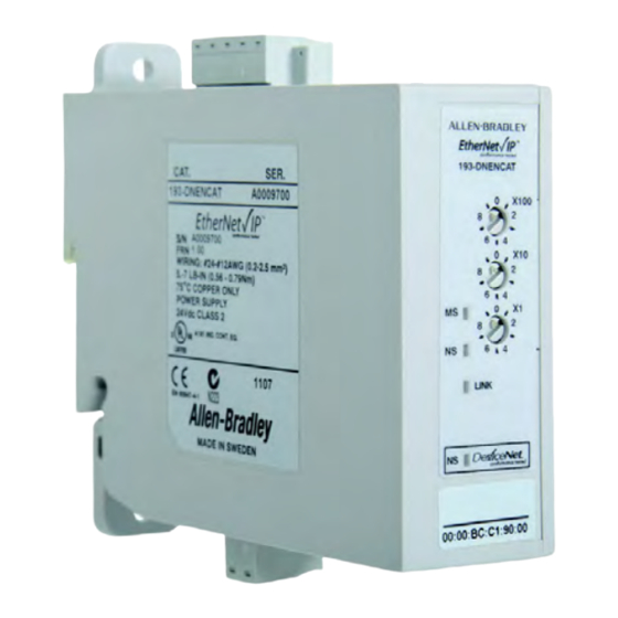
Installation and Wiring Chapter 1 Features Figure 1 - Features Front View Top View Ethernet Connectors Module RJ-45 Status EtherNet/IP LEDs Network Activity Front Port Link LEDs Rear Port Link DeviceNet Network Status LED Side View Rear View DeviceNet Connector Panel Mounting Rail Mounting Earth Ground Connector... -
Page 14: Wiring
Chapter 1 Installation and Wiring Figure 2 - Installation Front View 37.44 mm (1-1/2 in.) 37.44 mm (1-1/2 in.) Wiring The EtherNet/IP Communication Auxiliary Module can accept all forms of DeviceNet cable. However, DeviceNet shielded cable is recommended. The module complies with the Open Device Vendors Association (ODVA) DeviceNet compliance testing when the distance between end nodes is 100 m or less with 60 or fewer network drops. -
Page 15: Dimensions
Installation and Wiring Chapter 1 Figure 3 - Wiring Diagram DNET (Black) 24V - CAN L (Blue) Shield CAN H (White) DNET (Red) 24V + Earth Ground ATTENTION: Use a shielded DeviceNet cable to comply with CISPR 22 and CISPR 24. Dimensions Figure 4 - Dimension Diagram Dimensions are shown in millimeters (inches). -
Page 16: Network Design
Network Design The EtherNet/IP Communication Auxiliary Module is available as a single Ethernet port (Cat. No. 193-DNENCAT) and dual Ethernet port (Cat. No. 193-DNENCATR) module that has RJ45 ports to connect to Ethernet cable CAT5 type or better. Rockwell Automation offers a wide variety of... - Page 17 Installation and Wiring Chapter 1 Figure 6 - Ring Ethernet Topology The Cat. No. 193-DNENCATR Module supports the Rockwell Automation Device Level Ring (DLR) topology as a slave device in which the EtherNet/IP network still continues to communicate if one of the network chains is disrupted.
- Page 18 Chapter 1 Installation and Wiring Notes: Rockwell Automation Publication 193-UM014C-EN-P - August 2016...
- Page 19 Chapter Configure the EtherNet/IP Communication Auxiliary Module Introduction This chapter describes how to configure an EtherNet/IP communication auxiliary module to operate on an EtherNet/IP network. When you first install an EtherNet/IP communication auxiliary module, the module is Dynamic Host Configuration Protocol (DHCP) enabled. Determining Network To operate an EtherNet/IP network, you must define these parameters.
-
Page 20: Setting The Ip Network Address
Chapter 2 Configure the EtherNet/IP Communication Auxiliary Module Table 3 - EtherNet/IP Network Parameters for DNS Addressing Network Parameter Description A host name is part of a text address that identifies the module. The full Host Name text address of a module is: host_name.domain_name. A domain name is part of a text address that identifies the domain in Domain Name which the module resides. -
Page 21: Assign Network Parameters Via The Bootp/Dhcp Utility
Configure the EtherNet/IP Communication Auxiliary Module Chapter 2 Figure 7 - Last Octet Selection x 100 Digit x 10 Digit x 1 Digit EXAMPLE When the top dial is set to 1, the middle dial is set to 2, and the bottom dial is set to 3, the resulting IP address is: 192.168.1.123. - Page 22 Chapter 2 Configure the EtherNet/IP Communication Auxiliary Module 3. If appropriate for the network, type the subnet mask, gateway address, primary/secondary server addresses, and domain name in their respective fields. 4. Click OK. The Request History panel displays the hardware addresses of modules issuing BOOTP or DHCP requests.
-
Page 23: Software
Configure the EtherNet/IP Communication Auxiliary Module Chapter 2 The New Entry window appears with the module’s media access control address (MAC). 6. Type the IP address, host name, and a module description. 7. Click OK. 8. Cycle power to the module by removing and reapplying the DeviceNet connector. - Page 24 Chapter 2 Configure the EtherNet/IP Communication Auxiliary Module 4. Select the appropriate subnet to scan for available MAC addresses. 5. Scan the Subnet for all available MAC addresses. 6. Identify the IP address assigned to the MAC ID of the EtherNet/IP communication auxiliary module.
-
Page 25: Network Parameters
Configure the EtherNet/IP Communication Auxiliary Module Chapter 2 10. Assign the appropriate network settings per the recommendation of the network administrator for the network that this module communicates on and click Apply. 11. Remove and reapply the DeviceNet connector to allow the communications changes to take effect. -
Page 26: Duplicate Ip Address Detection
Chapter 2 Configure the EtherNet/IP Communication Auxiliary Module module. In this case, disconnect the uplink to set the address and configure the module to retain its static address before reconnecting to the uplink. This is not a problem if you have node names configured in the module and leave DHCP enabled. -
Page 27: Dns Addressing
EDS file. You can obtain the EDS file for the EtherNet/IP communication auxiliary module from one of two locations: • embedded in the module OR • the Allen-Bradley EDS file download website. Download the EDS File Embedded in the Module The EDS file for the EtherNet/IP communication auxiliary module is embedded within the module. - Page 28 From the EDS File Download Site The EDS file for the EtherNet/IP communication auxiliary module can also be downloaded from the Allen-Bradley EDS File download site. Using a web browser on the personal computer that is connected to the internet, you can download the EDS file by following these steps: 1.
-
Page 29: Register The Eds File
Configure the EtherNet/IP Communication Auxiliary Module Chapter 2 2. Select EtherNet/IP as the network type, then click Search. 3. Locate the EDS file for the EtherNet/IP communication auxiliary module and download it to the personal computer. Register the EDS File After the EDS file has been downloaded, you need to register the EDS file with the software that configures the EtherNet/IP network. - Page 30 Chapter 2 Configure the EtherNet/IP Communication Auxiliary Module 1. Start the EDS Hardware Installation Tool located at Start>Programs> Rockwell Software>RSLinx Tools. 2. Click Add to register a new device. 3. Click the “Register a single file” radio button, then browse to the location where the EDS file is located.
- Page 31 Configure the EtherNet/IP Communication Auxiliary Module Chapter 2 4. Click Next to accept the installation test results. 5. Click Next to accept the graphic image. Rockwell Automation Publication 193-UM014C-EN-P - August 2016...
-
Page 32: Web Server
Chapter 2 Configure the EtherNet/IP Communication Auxiliary Module 6. Click Next to register the device. 7. Click Finish to successfully register the module. Web Server Use the embedded web server of the EtherNet/IP communication auxiliary module to configure the DeviceNet scanner and view diagnostic information of the EtherNet/IP communication auxiliary module. -
Page 33: Permanently Enabling The Web Server
Configure the EtherNet/IP Communication Auxiliary Module Chapter 2 EtherNet/IP communication auxiliary module back to their original position and cycle power. The EtherNet/IP Communication Auxiliary Web Server will be disabled unless it was permanently enabled. Permanently Enabling the Web Server In Administrative Mode, you can change any configuration parameter of the EtherNet/IP communication auxiliary module, including permanently enabling the embedded web server by following these steps: 1. - Page 34 Chapter 2 Configure the EtherNet/IP Communication Auxiliary Module Notes: Rockwell Automation Publication 193-UM014C-EN-P - August 2016...
-
Page 35: Configuration
Chapter Configure the DeviceNet Network Introduction This chapter helps you to configure the DeviceNet Network by using the EtherNet/IP communication auxiliary module. You can configure a DeviceNet network by using the internal web interface from the EtherNet/IP communication auxiliary module. Configuration 1. - Page 36 Chapter 3 Configure the DeviceNet Network 3. Type the size of the Scan List I/O Entry in the field. The entry size determines the number of input and output bytes that the EtherNet/IP communication auxiliary module scans from each of the scanned devices.
- Page 37 Configure the DeviceNet Network Chapter 3 6. Change the DeviceNet network address to the appropriate node address, then click Save. NOTE: Typically, DeviceNet scanners have the node address of 0. 7. Click OK to finish changing the scanner DeviceNet network address. Rockwell Automation Publication 193-UM014C-EN-P - August 2016...
- Page 38 Chapter 3 Configure the DeviceNet Network Notes: Rockwell Automation Publication 193-UM014C-EN-P - August 2016...
- Page 39 Chapter Add Devices to the DeviceNet Network Introduction This chapter describes how to assign an address to each DeviceNet module and configure the DeviceNet scanner to scan up to six modules. DeviceNet Node Addressing Each module that you add to the DeviceNet network must have a unique network mode address.
-
Page 40: Node Address Basics
Chapter 4 Add Devices to the DeviceNet Network Node Address Basics • Verify the node address assigned to the new device. • Prevent duplicate node address assignments. – When connecting new DeviceNet modules with the Node Commissioning tool from the EtherNet/IP communication auxiliary module web interface, place one new DeviceNet module on the network at a time. -
Page 41: Using The Devicenet Node Commissioning Tool
Add Devices to the DeviceNet Network Chapter 4 2. Change the node address using the appropriate mechanism for the new device. Mechanism Procedure Rotary Switch Turn the rotary switch dials to the desired node address value. Usually, a small, flathead screwdriver is needed to turn the dials. Once the device is powered up, the rotary switch settings are recognized. - Page 42 Chapter 4 Add Devices to the DeviceNet Network 1. From the EtherNet/IP communication auxiliary module web page, navigate to Scan List>Configuration>Node Commissioning. 2. Select the device where node address needs to be assigned. Once you have selected the proper device, the software populates the Current Settings and New Settings areas.
- Page 43 Add Devices to the DeviceNet Network Chapter 4 4. Use the number keypad on the computer keyboard to change the network node address to the desired value, then click Apply. Make sure that the desired value does not duplicate the node address of any other device.
-
Page 44: Add Devicenet Modules To The Scan List
Chapter 4 Add Devices to the DeviceNet Network 6. In the 'New settings' section, verify that the node address was changed to the desired value. Note that the 'Current settings' area still displays the old node address until you select the device again from the Network Who list.Verify the node address was changed to the desired value in the “New settings”... -
Page 45: Simple
Add Devices to the DeviceNet Network Chapter 4 Simple 1. From the EtherNet/IP communication auxiliary module web page, navigate to Scan List>Configuration>Scan List. The EtherNet/IP communication auxiliary module reads the available DeviceNet modules on the DeviceNet network. 2. Click Config. The lowest six DeviceNet node addresses populate into the Scan List field on the right. -
Page 46: User-Defined
Chapter 4 Add Devices to the DeviceNet Network User-Defined If there are more than six DeviceNet devices on the network, you can select up to six DeviceNet devices to scan. Follow the steps below to select specific DeviceNet devices for the scan list. 1. - Page 47 Add Devices to the DeviceNet Network Chapter 4 6. Click OK to complete the scan list configuration. Rockwell Automation Publication 193-UM014C-EN-P - August 2016...
- Page 48 Chapter 4 Add Devices to the DeviceNet Network Notes: Rockwell Automation Publication 193-UM014C-EN-P - August 2016...
-
Page 49: Introduction
Chapter View and Configure Parameters Introduction This chapter tells you how to view and configure parameters for a DeviceNet device that supports the full implementation of the Parameter Object. View and Edit The EtherNet/IP communication auxiliary module can view and configure parameters for a DeviceNet device that supports the full implementation of the Parameter Object. - Page 50 Chapter 5 View and Configure Parameters 2. Click the Identity folder. The Identity tab appears, providing information about the selected device. 3. Click the Parameter folder. Subfields for this folder appear. Rockwell Automation Publication 193-UM014C-EN-P - August 2016...
- Page 51 View and Configure Parameters Chapter 5 4. Select a parameter group. A list of up to 15 parameters is displayed. If more than 15 parameters are available, select the page number or use the navigation arrows to view the additional parameter screens. TIP To increase the update rate of the data being displayed on the screen, lower the value in the “Seconds before refresh:”...
- Page 52 Chapter 5 View and Configure Parameters 6. Click the down arrow on the pull-down boxes to adjust fixed values and/ or enter numerical values in the fields without an arrow to adjust the values. 7. Click Apply once all parameter edits have been completed. The EtherNet/IP communication auxiliary module downloads the new parameter values to the device.
-
Page 53: Introduction
Chapter Automatic Device Recovery or Replace Introduction This chapter explains how to use the Automatic Device Recovery or Replace (ADR) feature. Using this feature reduces downtime if you need to replace a device. With the ADR feature, you do not need software tools to get a replacement device configured and online. - Page 54 Chapter 6 Automatic Device Recovery or Replace By default, the Device Type, Vendor, and Product Code are enabled. Electronic keying defines how closely a replacement device must match a failed device before the EtherNet/IP Auxiliary reconfigures a module. If the new module does not match the criteria of one of the checked boxes, the ADR does not function and an ADR error appears.
- Page 55 Automatic Device Recovery or Replace Chapter 6 5. Click Save, then cycle power on the EtherNet/IP communication auxiliary module. An ADR download is performed immediately before the DeviceNet master allocates an I/O connection. For an ADR download to occur, the PLC must be online and scanning.
- Page 56 Chapter 6 Automatic Device Recovery or Replace the electronic key is detected on node 63, the module attempts to change its network node address to that of the missing scan list node number. When successful, the EtherNet/IP communication auxiliary module downloads the ADR information to the module.
-
Page 57: Introduction
Chapter Automation Controller Communication Introduction This chapter describes and gives examples of how EtherNet/IP messaging, I/O messaging, and Explicit Messaging are used. EtherNet/IP Messaging The EtherNet/IP communication auxiliary module supports two types of EtherNet/IP messaging. • I/O Messaging — Used for deterministic EtherNet/IP communications with ControlLogix™, CompactLogix™, SoftLogix™, and EtherNet/IP scanners. - Page 58 Chapter 7 Automation Controller Communication 1. Select File>New from the RSLogix 5000. 2. Select the controller type, chassis type, slot number, and project path. Then, enter a name for the controller and click OK. 3. Right-click the I/O Configuration folder, then select New Module. The Select Module Type window appears.
-
Page 59: Ethernet/Ip Network Configuration With Add-On Profiles
Automation Controller Communication Chapter 7 4. Select the desired EtherNet/IP scanner module, then click OK. 5. Enter the desired communication settings, then click Finish. EtherNet/IP Network Configuration with Add-on Profiles After the controller configuration, the EtherNet/IP communication auxiliary module has to be added to the I/O configuration. Rockwell Automation Publication 193-UM014C-EN-P - August 2016... - Page 60 2. Right-click the EtherNet/IP scanner within the I/O Configuration folder, then select New Module to open the Select Module Type window. 3. Select the appropriate device (either 193-DNENCAT or 193- DNENECATR, then click OK. Rockwell Automation Publication 193-UM014C-EN-P - August 2016...
- Page 61 Automation Controller Communication Chapter 7 4. Enter a name for the EtherNet/IP communication auxiliary module. The name creates tags in RSLogix 5000 that can be used to read and write data from DeviceNet modules being scanned by the EtherNet/IP communication auxiliary module. 5.
-
Page 62: Accessing Module Data With Add-On Profiles
Chapter 7 Automation Controller Communication 8. Click OK at the next window to have RSLogix 5000 create the predefined tags. The EtherNet/IP communication auxiliary module now shows as a module in the I/O Configuration folder. Accessing Module Data with Add-on Profiles With both the Logix controller and EtherNet/IP network configured, the Logix controller can exchange data with the EtherNet/IP communication auxiliary module. -
Page 63: Controllogix Generic Configuration
Automation Controller Communication Chapter 7 ControlLogix Generic Configuration An existing project can be used or a new project can be created to configure EtherNet/IP I/O Messaging. To create a new project, perform the following steps. 1. Select File>New from the RSLogix 5000. 2. -
Page 64: Ethernet/Ip Generic Module Configuration
Chapter 7 Automation Controller Communication 4. Select the desired EtherNet/IP scanner module, then click OK. 5. Enter the desired communication settings, then click Finish. EtherNet/IP Generic Module Configuration Once the Logix controller has been configured, the EtherNet/IP communication auxiliary module must be added to the I/O configuration. Rockwell Automation Publication 193-UM014C-EN-P - August 2016... - Page 65 Automation Controller Communication Chapter 7 1. Place the program in offline mode. 2. Right-click the EtherNet/IP scanner within the I/O Configuration folder, then select New Module to open the Select Module Type window. 3. Select Generic Ethernet Module, then click OK. Rockwell Automation Publication 193-UM014C-EN-P - August 2016...
- Page 66 Chapter 7 Automation Controller Communication 4. Enter a name for the EtherNet/IP communication auxiliary module. The name creates a tag in RSLogix 5000 that can be used to read and write data from the devices being scanned by the EtherNet/IP communication auxiliary module.
- Page 67 Automation Controller Communication Chapter 7 With firmware revision 3.000 and later, I/O data can be accessed using Input Instance 104 and Output Instance 105. The size of the input connection and the output connection shall correspond to the chosen instance. When choosing Input Instance 104, set the data size to 88.
-
Page 68: Accessing Generic Module Data
Chapter 7 Automation Controller Communication Accessing Generic Module Data With both the ControlLogix controller and the EtherNet/IP network configured, the ControlLogix controller can exchange data with the EtherNet/ IP communication auxiliary module. 1. Go online, then switch the controller to Remote Run mode. 2. - Page 69 Automation Controller Communication Chapter 7 Table 7 - Output Assembly — Instance 105 Byte Size Contents Command Register Bit 0 = Scanlist Config Bit 1 = ADR Record Scan List I/0 Size Data to be delivered to the first scan list entry Scan List I/0 Size Data to be delivered to the second scan list entry Scan List I/0 Size...
-
Page 70: Logic Explicit Messaging
Chapter 7 Automation Controller Communication Table 9 - Input Assembly — Instance 104 Byte Size Contents Reserved (Must be 0) Scanner Status Word (Parameter 1) Scanner Node Address Scan List Entry 1 Status Word (Parameter 2) See Table 12 on page 82 Scan List Entry 1 Node Address Scan List Entry 2 Status Word (Parameter 3) See Table 13 on page 82... - Page 71 Automation Controller Communication Chapter 7 1. In an integer array named MSG_Read_Request, define the number of attributes to read and list the specific attribute numbers. The MSG instruction returns in an integer array with the first integer representing the following information: •...
- Page 72 Chapter 7 Automation Controller Communication 2. Set up the MSG instruction in the Configuration tab to read the list of attributes (Parameters Group) by configuring the following fields: • Message Type: CIP Generic • Service Type: Custom • Service Code: 0x03 (hex) •...
- Page 73 Automation Controller Communication Chapter 7 4. Click OK. When finished, the MSG instruction reads the 25 parameters from the E3 Overload Relay and places the results into MSG_Read_Data as shown below. Rockwell Automation Publication 193-UM014C-EN-P - August 2016...
- Page 74 Chapter 7 Automation Controller Communication Notes: Rockwell Automation Publication 193-UM014C-EN-P - August 2016...
-
Page 75: Introduction
Chapter Email/Text Introduction This chapter describes email notifications and how to configure an EtherNet/IP communication auxiliary module to send email messages and text notifications for different communication events. Email Notifications Events Several communication events can trigger email notifications. These events are fault conditions for the DeviceNet scan list and EtherNet/IP communication auxiliary module. -
Page 76: Email Configuration
Chapter 8 Email/Text EXAMPLE Email Subject: 193-DNENCATR Comms Aux has detected a fault Email Body: Fault Status: Device Name: 193-DNENCATR Comms Aux Device Description: Motor Starters Device Location: Bay 6-U29 Contact Info: Contact Person contactperson@thecontact.com The first word in the email subject is the device name. If a device name is not configured, then the product name attribute from the identity object is used. -
Page 77: Configure Device Identity
Email/Text Chapter 8 If desired, you can set a password within the Administrative Settings tab. 4. Type the information into the email notification fields as shown. Email Recipient The email address of the person who receives the notifications. Email Sender The email address from which the notification is sent. -
Page 78: Text Notifications
Chapter 8 Email/Text 2. Type the Device Identity information into the fields as described below. Device Name The name of the EtherNet/IP communication auxiliary module. Device Description The description of the EtherNet/IP communication auxiliary module. Device Location The location of the EtherNet/IP communication auxiliary module. Contact Information The contact information for the EtherNet/IP communication auxiliary module. -
Page 79: Limitations
Email/Text Chapter 8 Limitations Based on the functionality of the EtherNet/IP communication auxiliary module, there are some limitations on when the emails can be triggered. • If two events occur simultaneously, an email is only sent for the most significant error. •... - Page 80 Chapter 8 Email/Text Notes: Rockwell Automation Publication 193-UM014C-EN-P - August 2016...
-
Page 81: Introduction
Chapter Device Parameters Introduction The EtherNet/IP communication auxiliary module provides parameters to let you view the status and configure the DeviceNet scanner with RSNetWorx™ for DeviceNet if you do not want to use the internal web server of the EtherNet/IP communication auxiliary module. Table 10 lists the 14 available parameters. - Page 82 Chapter 9 Device Parameters Table 12 - Parameter 2 — SL Entry 1 Status Value Description Access Rule Data Type Units Min. Max. Default Provides the status of the first scan list entry in the DeviceNet WORD — 2047 scanner. 0 On Line 4 No Such Device Device Went Idle...
- Page 83 Device Parameters Chapter 9 Table 15 - Parameter 5 — SL Entry 4 Status Value Description Access Rule Data Type Units Min. Max. Default Provides the status of the fourth scan list entry in the DeviceNet WORD — 2047 scanner. 0 On Line 4 No Such Device Device Went Idle...
- Page 84 Chapter 9 Device Parameters Table 19 - Parameter 9 — Device Keys Value Description Access Rule Data Type Units Min. Max. Default Determines how electronic Get/Set USIN T — keying is performed. 0 Device Type 2 Product Code 4 Minor Revision 1 Vendor 3 Major Revision 5 Minor of Higher...
-
Page 85: Introduction
Chapter Troubleshooting Introduction This chapter helps you to troubleshoot the EtherNet/IP communication auxiliary module. SHOCK HAZARD: Servicing energized industrial control equipment can be hazardous. Electrical shock, burns, or unintentional actuation of controlled industrial equipment may cause death or serious injury. For safety of maintenance personnel and others who may be exposed to electrical hazards associated with maintenance activities, follow local safety-related work practices (for example, the NFPS 70W;... -
Page 86: Power-Up Reset Mode
Chapter 10 Troubleshooting Power-Up Reset Mode Figure 8 - Status LEDs Module Status (MS) LED Ethernet/IP Network Status (NS) LED Front Port Link Activity LED Rear Port Link Activity LED DeviceNet Network Status (NS) LED During the Power-Up Reset mode, the following procedure occurs. 1. -
Page 87: Run Mode
Troubleshooting Chapter 10 3. The EtherNet/IP communication auxiliary module performs a duplicate media access control (MAC) address check to verify that another module is not assigned to the same MAC address. If a duplicate MAC address is detected on the DeviceNet network, the DeviceNet NS status indicator illuminates a solid red, the MS status indicator flashes red, and the EtherNet/IP communication auxiliary module enters the Recoverable Error mode. -
Page 88: Rockwell Automation Publication 193-Um014C-En-P - August
Chapter 10 Troubleshooting Recoverable Error Mode In this mode, the EtherNet/IP communication auxiliary module MS LED flashes red. The device responds to messages that are specified in offline mode recovery message protocol. Error Type Description LED State Duplicate IP address detected. Recoverable Flashing Red A device is not present on the DeviceNet scan list. - Page 89 Troubleshooting Chapter 10 Status LED Color State Possible Cause Corrective Action Check the DeviceNet cable The EtherNet/IP communication connections and verify that 24V None — auxiliary module is not receiving DC exists between the red and power. black terminals. Green, Red, Flashing This is a normal power-up Normal...
- Page 90 Chapter 10 Troubleshooting Notes: Rockwell Automation Publication 193-UM014C-EN-P - August 2016...
-
Page 91: Specifications
Appendix Specifications Specifications Table 26 - Ratings Terminal Ratings Terminal Screw Wire Cross Section See wiring diagram section Torque 0.56…0.79 N•m (5…7 lb.•in.) Degree of Protection IP20 Power Supply Ratings Rated Supply Voltage 24V DC Rated Operating Range 24V -15%, +10% DC Rated Supply Current 100 mA at 24V DC Maximum Surge Current at Power-Up... - Page 92 Appendix A Specifications Table 27 - Electromagnetic Compatibility Electromagnetic Compatibility Electrostatic Discharge Immunity Test Level 8 kV Air Discharge 4 kV Contact Discharge (1) (2) Performance Criteria RF Immunity Test Level 10V/m: 80 MHz…1 GHz 3V/m: 1.4 GHz…2 GHz 1V/m: 2.0 GHz…2.7 GHz (1)(2) Performance Criteria Electrical Fast Transient/Burst Immunity...
-
Page 93: Electronic Data Sheet (Eds) Files
Appendix EtherNet/IP and DeviceNet Information Electronic Data Sheet (EDS) EDS files are specially formatted ASCII files that provide all of the information necessary for a configuration tool (for example, RSNetWorx™ for Files EtherNet/IP) to access and alter the parameters of a device. The EDS file contains all the parameter information of a device: number of parameters, groupings, parameter name, min, max, and default values, units, data format and scaling. -
Page 94: Message Router Object — Class Code 0X02
Attribute ID Access Rule Name Data Type Value Vendor ID UINT Device Type UINT 220 for 193-DNENCAT Product Code UINT 221 for 193-DNENCATR Major Revision USINT Minor Revision USINT Bit 0: Owned, shall be set when at least one connection is configured... -
Page 95: Assembly Object — Class Code 0X04
EtherNet/IP and DeviceNet Information Appendix B Table 35 - Single Instance of the DeviceNet Object Attribute ID Access Rule Name Data Type Value Get/Set Node Address USINT 0-63 0=125K Get/Set Baud Rate USINT 1=250K 2=500K Identifies which nodes are online on the local Active Node Table Array of BOOL [64] network based on the... - Page 96 Appendix B EtherNet/IP and DeviceNet Information Table 40 - Output Assembly — Instance 105 (available with firmware v 3.00 and higher) Byte Size Contents Command Register Bit 0 = Scanlist Config Bit 1 = ADR Record Scan List I/0 Size Data to be delivered to the first scan list entry Scan List I/0 Size Data to be delivered to the second scan list entry...
- Page 97 EtherNet/IP and DeviceNet Information Appendix B Table 42 - Instance 103 (available with firmware v 2.00 and higher) Byte Size Contents 4 Bytes Logix Status Word 4 Bytes DeviceNet Scanner Status (Parameter 1) See Table 11 on page 81 4 Bytes Scan List Entry 1 Status Word (Parameter 2) See Table 12 on page 82 4 Bytes...
- Page 98 Appendix B EtherNet/IP and DeviceNet Information Table 43 - Input Assembly — Instance 104 (available with firmware v 3.00 and higher) Byte Size Contents Reserved (Must be 0) Scanner Status Word (Parameter 1) Scanner Node Address Scan List Entry 1 Status Word (Parameter 2) See Table 12 on page 82 Scan List Entry 1 Node Address Scan List Entry 2 Status Word (Parameter 3) See...
- Page 99 EtherNet/IP and DeviceNet Information Appendix B Configuration Assembly Table 44 - Instance 102 (Revision 1) Byte Size Contents 2 Bytes Revision = 1 2 Bytes ScanList I/O Size 2 Bytes Data Link Update Interval (ms) 1 Byte Data Link 1 Node 2 Bytes Data Link 1 Parameter 1 Byte...
- Page 100 Appendix B EtherNet/IP and DeviceNet Information Table 45 - Instance 102 (Revision 2) (available with firmware v 2.00 and higher) Byte Size Contents 2 Bytes Revision = 2 2 Bytes ScanList I/O Size 2 Bytes Data Link Update Interval (ms) 2 Bytes Reserved 2 Bytes...
- Page 101 EtherNet/IP and DeviceNet Information Appendix B Byte Size Contents Scan List 2 Major Revision Scan List 2 Minor Revision Scan List 3 Node Address Scan List 3 Vendor ID Scan List 3 Device Type Scan List 3 Product Code Scan List 3 Major Revision Scan List 3 Minor Revision Scan List 4 Node Address Scan List 4 Vendor ID...
-
Page 102: Connection Manager Object — Class Code 0X06
Appendix B EtherNet/IP and DeviceNet Information The following services are implemented for the Assembly Object. Table 47 - Ethernet Object Common Services Implemented for: Service Code Service Name Class Instance Consuming Instance Producing 0x0E Get Attribute Single 0x10 Set Attribute Single Connection Manager Object —... -
Page 103: Device Level Ring (Dlr) Object — Class Code 0X47
EtherNet/IP and DeviceNet Information Appendix B The following instance attributes are implemented for all parameter attributes. Table 50 - Parameter Object Instance Attributes Attribute ID Access Rule Name Data Type Value Get/Set Value Specified in Descriptor Link Path Size USINT Path to specified object Link Path Packed EPATH:... -
Page 104: Qos Object — Class Code 0X48
Appendix B EtherNet/IP and DeviceNet Information Table 52 - DLR Object Single Instance Attributes ID Access Rule Name Data Type Value 0=Linear Network Topology USINT 1=Ring 0=Normal 1=Ring Fault Network Status USINT 2=Unexpected Loop Detect 3=Partial Network Fault 4=Rapid Fault/Restore Cycle Structure of UDINT;... -
Page 105: Port Object — Class Code 0X0F4
EtherNet/IP and DeviceNet Information Appendix B Port Object — CLASS CODE 0x0F4 The Port object supports the following class attributes. Table 57 - Port Object Class Attributes Attribute ID Access Rule Name Data Type Value Revision UINT Max. Instance UINT Num. -
Page 106: Ethernet Link Object — Class Code 0Xf6
Appendix B EtherNet/IP and DeviceNet Information For single port devices, one instance of the TCP/IP interface object is supported. For dual port devices, two instances of the TCP/IP interface object are supported. Table 61 - TCP/IP Object Class Instances Attribute ID Access Rule Name Data Type... - Page 107 EtherNet/IP and DeviceNet Information Appendix B Table 64 - Ethernet Link Object Instance Attribute ID Access Rule Name Data Type Value Interface Speed UDINT 10 or 100 Mbit/sec Interface Flags DWORD See ENet/IP Spec Physical Address ARRAY of 6 USINTs MAC Address Struct of: In Octets...
- Page 108 Appendix B EtherNet/IP and DeviceNet Information Notes: Rockwell Automation Publication 193-UM014C-EN-P - August 2016...
-
Page 109: Index
Index DeviceNet IP addresses ?? … CIP object 94 duplication address detection accessing module data 68 information 93 set 20 add-on profiles 57 DeviceNet modules swapping in redundant systems 26 accessing module data 62 adding to scan list 44 ControlLogix configuration 57 DeviceNet network EtherNet/IP Network configuration 59 add devices 39... - Page 110 Index operation modes 85 Wire 14 Wiring 11 power-up reset 86 recoverable error 88 Diagram 15 run 87 unrecoverable error 88 overview 11 parameter CIP object 102 configure 49 device 81 edit 49 listing 81 programming 81 view 49 port object 105 ports 16 programming parameters 81 QoS object 104...
- Page 112 How Are We Doing? form at http://literature.rockwellautomation.com/idc/groups/literature/documents/du/ra-du002_-en-e.pdf. Rockwell Automation maintains current product environmental information on its website at http://www.rockwellautomation.com/rockwellautomation/about-us/sustainability-ethics/product-environmental-compliance.page. Allen-Bradley, ContgrolLogix, Rockwell Software, Rockwell Automation, RSLogix, and TechConnect are trademarks of Rockwell Automation, Inc. Trademarks not belonging to Rockwell Automation are property of their respective companies.
Need help?
Do you have a question about the 193-DNENCAT and is the answer not in the manual?
Questions and answers