Table of Contents
Advertisement
ControlNet-to-DeviceNet Linking Device
Catalog No. 1788-CN2DN
Product Overview
The ControlNet-to-DeviceNet (CN2DN) linking device connects a ControlNet™
network to a DeviceNet™ network. The DeviceNet network consists of multiple
DeviceNet devices, such as RediSTATIONs, photoeyes, etc. The ControlNet
network consists of controllers, such as PLC® processors, HMIs, drives, I/O
devices, and so on.
The CN2DN linking device has two broad functions, supporting closed-loop
control, and configuration and monitoring.
To the Installer
Use this document as a guide when you install the 1788-CN2DN.
.
Topic
System Requirements
CN2DN Hardware Description
Installing the CN2DN Module
ControlNet Connections
DeviceNet Connections
Setting the DNet Data Rate
Setting the Node Address Switches
The Example Installation
RSLogix5000™ Setup
ControlNet Setup Using RSNetWorx for ControlNet
DeviceNet Setup Using RSNetWorx for DeviceNet
Interpreting the Status Indicators
Compliance to European Union Directives
CSA Hazardous Location Approval
Specifications
Installation Instructions
1788-5.2B - October 1999
Page
3
4
4
6
9
11
10
12
12
17
21
27
31
32
34
Advertisement
Table of Contents

Subscribe to Our Youtube Channel
Related Manuals for Allen-Bradley ControlNet-to-DeviceNet 1788-CN2DN


Summary of Contents for Allen-Bradley ControlNet-to-DeviceNet 1788-CN2DN
- Page 1 Installation Instructions ControlNet-to-DeviceNet Linking Device Catalog No. 1788-CN2DN Product Overview The ControlNet-to-DeviceNet (CN2DN) linking device connects a ControlNet™ network to a DeviceNet™ network. The DeviceNet network consists of multiple DeviceNet devices, such as RediSTATIONs, photoeyes, etc. The ControlNet network consists of controllers, such as PLC® processors, HMIs, drives, I/O devices, and so on.
- Page 2 Since there are many variables and requirements associated with any particular installation, Allen-Bradley does not assume responsibility or liability (to include intellectual property liability) for actual use based upon the examples shown in this publication.
-
Page 3: System Requirements
• ControlNet and DeviceNet cabling Software • Windows NT® 4.0 with service pack 3 or higher • RSLinx 2.10 or later; this is the driver for the Allen-Bradley PC interfaces. • RSNetWorx™ for ControlNet version 2.0 or later; this is the ControlNet configuration tool. -
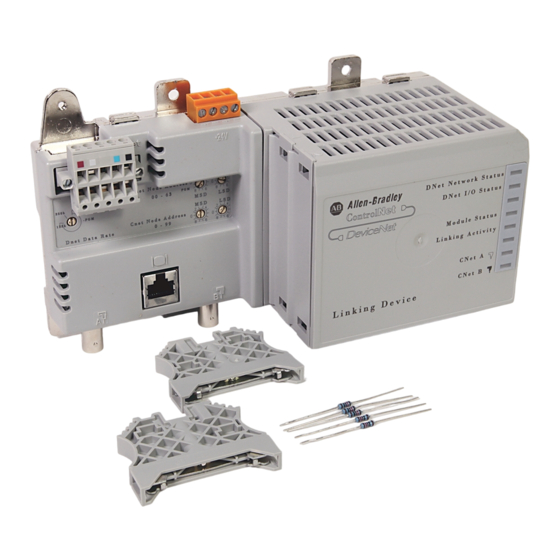
Page 4: Cn2Dn Hardware Description
ControlNet-to-DeviceNet Linking Device CN2DN Hardware Description Figure 1 shows the components of the CN2DN linking device. Figure 1 CN2DN Linking Device Power Supply Status LEDs Connector DeviceNet Port DIN Rail Rotary Switches Network End Anchor End Anchor Access 30901-M Port ControlNet Port The CN2DN module is designed to be mounted on a 35 mm steel DIN rail. -
Page 5: Installing The Cn2Dn Module
ControlNet-to-DeviceNet Linking Device Installing the CN2DN Module The CN2DN module has a clip for mounting on a standard 35 mm steel DIN rail. Follow these steps to mount the CN2DN onto the DIN rail. Important: You must use a steel DIN rail (A-B P/N 199-DR1 or equivalent) to meet vibration specifications listed on page 34. -
Page 6: Connecting Power
ControlNet-to-DeviceNet Linking Device Removing the CN2DN module To remove the CN2DN module, simultaneously pull the 2 DIN rail latches away from the rail and pull the module off the panel. (Note: This may require two screwdrivers to open the latches.) Connecting Power The CN2DN linking device requires 18-26V dc input power. - Page 7 ControlNet-to-DeviceNet Linking Device ATTENTION: If you connect the product to a cable system that does not support redundant media, connect the tap dropline to the BNC connector labeled channel A. channel B is left open when using single media. If the cable system is redundant, connect all channel A connectors to one cable, and all channel B connectors to the other cable.
- Page 8 ControlNet-to-DeviceNet Linking Device Figure 6 shows an example of a typical ControlNet network connection. Figure 6 Typical CN2DN Connections to a ControlNet Network ControlNet Device Linking Device trunk cable B = trunk cable A = ControlNet Device 30907-M 1788-5.2B - October 1999...
-
Page 9: Devicenet Connections
ControlNet-to-DeviceNet Linking Device DeviceNet Connections The location of the DeviceNet connector is shown in figure 7. Figure 7 DeviceNet Connector on the CN2DN DeviceNet Connector 30902-M Use an open-style 5- or 10-position linear plug to connect to the DeviceNet network. An open-style 10-position linear plug is provided with your CN2DN. Wire the connector as shown in figure 8. -
Page 10: Setting The Node Address Switches
ControlNet-to-DeviceNet Linking Device Setting the Node Address Switches Important: When using a 1788-CN2DN, the ControlNet network must have an “Active Keeper” to keep track of network scheduling, clock synchronization, etc. Refer to publication 1756-5.71, ControlLogix ControlNet Bridge, for information on configuring a 1756-CNB module. CN2DN ControlNet Address Choose and set a ControlNet network address for the CN2DN. -
Page 11: Setting The Dnet Data Rate
ControlNet-to-DeviceNet Linking Device Setting the DNet Data Rate Set the data rate for your DeviceNet network: 125K, 250K, or 500K. Data rate settings in the PGM area are not supported. Refer to figure 11: Figure 11 DNet Data Rate Switch Parts 1788-5.2B - October 1999... -
Page 12: The Example Installation
ControlNet network to communicate with a Logix5550 controller. A 1756-CNB interface module must be in the chassis with the Logix5550 controller. Note that this is but one example. The CN2DN linking device can be used with any Allen-Bradley controller that is provided with a ControlNet interface. RSLogix5000 ™... - Page 13 ControlNet-to-DeviceNet Linking Device The software will save the New Controller data and the following screen will appear: I/O Configuration Next, you must add the 1756-CNB interface module to the I/O configuration of the controller. Then you will add the 1788-CN2DN linking device as a “child” of the 1756-CNB module.
- Page 14 ControlNet-to-DeviceNet Linking Device The following pop-up menu will appear. 2. Select New Module. The Select Module Type window will appear: 3. Select the 1756 ControlNet Bridge from the list and click on OK. 1788-5.2B - October 1999...
- Page 15 ControlNet-to-DeviceNet Linking Device The Module Properties window will appear: 4. Enter a Name for the ControlNet 1756-CNB module and select the chassis Slot it occupies. 5. Disable Electronic Keying. 6. Click on the button. The 1756-CNB module will be added to the I/O Configuration folder. Now add the 1788-CN2DN linking device to the I/O configuration by performing the following steps: 1.
- Page 16 ControlNet-to-DeviceNet Linking Device The Select Module Type window will appear. 3. Select the 1788-CN2DN ControlNet to DeviceNet Linking Device and click on OK (the 1788-CN2DN_04 Device is recommended). The Module Properties window will appear. 4. Enter a Name of you choice for the 1788-CN2DN module. 5.
-
Page 17: Controlnet Setup Using Rsnetworx For Controlnet
ControlNet-to-DeviceNet Linking Device The I/O configuration should now appear as shown below: ControlNet Setup Using RSNetWorx for ControlNet If you are using a ControlLogix 5550 processor, the following can be used as part of your setup. 1. Open the RSNetWorx for ControlNet software. 2. - Page 18 ControlNet-to-DeviceNet Linking Device The Browse for Network window will appear. Your window may appear different from that shown below depending upon the drivers you have installed in your system, but you should have a ControlNet driver (e.g., a 1784-KTCX15 card) configured. 3.
- Page 19 ControlNet-to-DeviceNet Linking Device 5. Select Network from the RSNetWorx for ControlNet main menu bar. 6. Select Properties from the pull-down menu. The following window will appear: 7. Set the following parameters to appropriate values for your system: • Network Update Time - 10 ms is a typical value Parts •...
- Page 20 ControlNet-to-DeviceNet Linking Device • Max Unscheduled Address - set to the highest node address used on your ControlNet (i.e., do not set to 99 unless you have 99 nodes on your network). 8. Click on OK. 9. From the File menu, select Save. The following prompt will appear: 10.Select “Optimize and re-write schedule for all connections”...
-
Page 21: Devicenet Setup Using Rsnetworx For Devicenet
ControlNet-to-DeviceNet Linking Device DeviceNet Setup Using RSNetWorx for DeviceNet 1. Open the RSNetWorx for DeviceNet software. 2. Click on the Online button The Browse for network \window will appear. (Your window may appear different from that shown below, depending upon the drivers installed on your system). - Page 22 ControlNet-to-DeviceNet Linking Device 3. Select the ControlNet driver (AB_KTC-1 in the window above) and drill down through the 1788-CN2DN Linking Device to the DeviceNet driver. 4. Click on OK. The following prompt will appear: 5. Click on OK to browse the network. When browsing is complete you should see all of the devices on your DeviceNet network.
- Page 23 ControlNet-to-DeviceNet Linking Device The following window will appear: 7. Select Properties. The following window will appear. 8. Select the Scanlist tab. Parts 1788-5.2B - October 1999...
- Page 24 ControlNet-to-DeviceNet Linking Device The Available devices on your network will be displayed. 9. Ensure that the Automap on Add box is checked. 10.Highlight the desired devices in the Available window, and move them to the Scanlist window with the (all devices) button. RediStation Output mapped Photoeye Input mapped to output address 7...
-
Page 25: Controller Interface
ControlNet-to-DeviceNet Linking Device Controller Interface The initial release of the 1788-CN2DN firmware supports a single default input, output, and status assembly over the ControlNet backplane. These default I/O structures were created to reduce the complexity of connecting DeviceNet I/O and status data with ladder programs. The module creates all 3 structures whether or not DeviceNet nodes are configured or online. -
Page 26: Input Structure
ControlNet-to-DeviceNet Linking Device Input Structure The controller receives input I/O by reading input data from an input structure in the 1788-CN2DN module. The scanner module receives input data from DeviceNet modules and delivers a copy of these values to the controller. The input structure consists of one 32-bit status register and an array of 1 to 124 32-bit words for input data. -
Page 27: Status Structure
ControlNet-to-DeviceNet Linking Device Status Structure The controller receives status information concerning the 1788-CN2DN module’s ability to exchange DeviceNet messages with other nodes by reading from a status structure in the 1788-CN2DN module. The scanner module periodically updates the contents of the status structure and copies its contents to the controller. -
Page 28: Module Status Led
ControlNet-to-DeviceNet Linking Device Module STATUS LED The Module Status LED indicates whether the CN2DN is powered, configured, and operating properly. Table A shows how to interpret the Module Status LED states. Table A Interpretation of the Module Status LED LED State Meaning No power to device Flashing green... -
Page 29: Devicenet Network Status Led
ControlNet-to-DeviceNet Linking Device ControlNet Network Status LEDs (CNet A, CNet B) The ControlNet Network Status LEDs indicate the state of the ControlNet network connected to the BNC connectors. If more than one state is present, the LEDs always reflect the highest priority status present on the network. Note that these LEDs do not reflect the status of the network access port (NAP). -
Page 30: Devicenet I/O Status Led
ControlNet-to-DeviceNet Linking Device DeviceNet I/O Status LED The DeviceNet I/O Status LED indicates the functional state of the I/O on the DeviceNet. Table E describes each state. Table E Description of DeviceNet I/O Status LED States LED State Meaning All inputs and outputs are inactive. Steady green One or more outputs are active and under control, and no outputs are faulted. -
Page 31: Compliance To European Union Directives
Part 2 - Equipment Requirements and Tests. For specific information required by EN 61131-2, see the appropriate sections in this publication, as well as the following Allen-Bradley publications: • Industrial Automation Wiring and Grounding Guidelines for Noise Immunity, publication 1770-4.1 •... -
Page 32: Csa Hazardous Location Approval
ControlNet-to-DeviceNet Linking Device CSA Hazardous Location Approval Hazardous Location Approval This product is certified for general use as well as for use in hazardous locations. Actual agency certification is indicated by the product label as shown below, and not by statements in any user documentation. - Page 33 ControlNet-to-DeviceNet Linking Device Approbation d’utilisation en environnements dangereux Ce produit est certifié pour une utilisation générale aussi bien que pour une utilisation en environnements dangereux. La certification en vigueur est indiquée par l'étiquette produit et non par des indications dans la documentation utilisateur. CL I, DIV 2 GP A,B,C,D TEMP...
-
Page 34: Specifications
ControlNet-to-DeviceNet Linking Device Specifications Type Specifications Dimensions Height:: 120mm (4 11/16 in) Depth: 87mm (3 7/16 in) Width: 200mm (7 7/8 in) Environmental Operating Temperature: 0 to 60° C (32 to 140° F) Storage Temperature: -40 to 85° C (-40 to 185° F) Relative Humidity: 5 to 90% (non-condensing) Vibration Operating - 2Gs each axis... - Page 35 ControlNet-to-DeviceNet Linking Device Parts 1788-5.2B - October 1999...
- Page 36 PLC is a trademark of Rockwell Automation. ControlNet is a trademark of ControlNet International. DeviceNet is a trademark of Open Device Vendors Association (ODVA). RSLinx, RSLogix5000, RSNetWorx are trademarks of Rockwell Software Inc. Windows NT is a trademark of Microsoft Corporation. Publication 1788-5.2B - October 1999 PN 955138-70 Supersedes Publication 1788-5.2 - July 1999...
Need help?
Do you have a question about the ControlNet-to-DeviceNet 1788-CN2DN and is the answer not in the manual?
Questions and answers