
Related Manuals for EdilKamin LILLE 8 Up


Summary of Contents for EdilKamin LILLE 8 Up
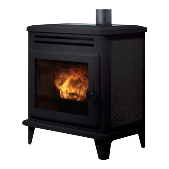
- Page 1 LILLE 8 PELLET STOVE For all updates visit www.edilkamin.com Installation, use and maintenance page...
- Page 2 The original language of this edition is Italian The undersigned company, EDILKAMIN S.p.A., with registered office in Via P . Moscati 8 - 20154 Milan (Italy) - Italian Tax ID VAT NO. 00192220192 Hereby declares, under its sole responsibility, that:...
-
Page 3: Meaning Of Symbols
• the declaration of conformity given to you by the installer. you can request a copy from your dealer or download it from www.edilkamin.com. The warranty conditions are given in the warranty certificate accompanying the product. Readers of the manual... -
Page 4: Safety Information
• Blocking the aeration vents and air intakes in the neither Edilkamin nor the retailer are liable for room. DO NOT BLOCK THE AERATION VENTS damage resulting from incorrect installation or OR FLUE. Risk of smoke returning into the room maintenance. - Page 5 DIMENSIONS DIMENSIONS (cm) Ø 8 predispo- sition for Ø 4 cm smoke outlet combustion air from behind 19.5 removable feet: stove height without feet 70 cm Ø 8 cm standard smoke outlet from above USER/INSTALLER...
-
Page 6: General Information
Fuse 4 AT 250 V AC 5x20 The above data are for guidance only and were measured during certification by a notified body. EDILKAMIN s.p.a. reserves the right to modify the product without notification in the interests of improvement. USER/INSTALLER... -
Page 7: Preparation And Unpacking
UNPACKING PREPARATION AND UNPACKING HOW TO REDUCE THE WEIGHT OF THE The packaging materials are neither toxic nor noxious The packaging materials are neither toxic nor noxious PRODUCT FOR HANDLING and do not require special disposal. and do not require special disposal. To reduce the weight of the product for handling you To reduce the weight of the product for handling you The user is responsible for storing, disposing of and... -
Page 8: Removing The Feet
REMOVING THE FEET At the base of the product there are four removable feet which can be removed to lower the product. The feet on each side consist of a single element which will be called “two feet assembly” (A) from now on Proceed as follows to remove them. - Page 9 REMOVING THE FEET 3. Remove the top and the pellet loading lid 4. Undo the two screws on each side on the brackets underneath the top 5. Slide the sides off (F) INSTALLER...
- Page 10 REMOVING THE FEET 6. Undo three screws per side of the feet assembly 7. Remove the feet assembly from each side (A) 8. Remove the adjustable feet (R) from the cast iron feet (P) to use them underneath the stove for levelling 9.
-
Page 11: Smoke Outlet
SMOKE OUTLET DIRECTION SMOKE OUTLET SMOKE OUTLET The stove can have its smoke outlet pipe connected to the top or the rear. The stove can have its smoke outlet pipe connected to the top or the rear. The stove is delivered with the smoke outlet pipe on the top. The stove is delivered with the smoke outlet pipe on the top. - Page 12 SMOKE OUTLET DIRECTION 4. refit the sides. 4. refit the sides. Use the metal cover provided with the product to close Use the metal cover provided with the product to close off the smoke outlet on the top. off the smoke outlet on the top. NOTE NOTE The top smoke outlet is female, the rear smoke outlet...
-
Page 13: Replacing The Knob
REPLACING THE KNOB The product has a knob (C Figure 1) on the handle of the combustion chamber door, with black as the standard colour. Operations are represented in the even number figures on this page. To replace it, if needed, proceed as follows. 1. -
Page 14: Installation
Contact the authorised Edilkamin Technical Assistance itself, or in any area with an explosive atmosphere. Centre. Any extraction fans operating in the same room or area as the product, may affect its draw. -
Page 15: Flue System
INSTALLATION FLUE SYSTEM FLUE SYSTEM • be certified, with a chimney plate if metal ( ( Smoke duct, flue and chimney pot Smoke duct, flue and chimney pot) ) • be of uniform cross section or vary in cross section This chapter has been drawn up pursuant to European only immediately after the outlet, not at some mid regulations EN 13384, EN 1443, EN 1856 and EN... -
Page 16: External Air Intake
INSTALLATION THE FLUE THE FLUE: EXTERNAL AIR INTAKE Further to the general prescriptions for the smoke duct In general, we suggest two ways to ensure a proper and flue, the flue: : flow of combustion air. • must serve solely to discharge smoke •... - Page 17 INSTALLATION FIRST IGNITION (COMMISSIONING) PHAS- LOADING THE PELLETS INTO THE TANK. To open the tank, lift the lid by using the handle* (use • Make sure you have read and understood this glove if hot) Make sure not to touch the smoke discharge pipe if manual hot.
-
Page 18: Operation
USER INSTRUCTIONS OPERATION The product also has the following supplementary Mode Settable parameters functions. MANUAL • power level • ventilation level (if there are Function Modes in which What it does two or more fans, they can be it can be acti- adjusted separately)* vated AUTOMATIC... - Page 19 USER INSTRUCTIONS INTERFACE The product can be managed alternatively as follows STANDARD • Bluetooth REMOTE CONTROL: can be used By purchasing the Edilkamin optional elements: for all functions, near the product • VOICE CONTROL SYSTEMS: Alexa or Google Home •...
-
Page 20: Optional Electrical Connections
OPTIONAL THERMOSTATS/PROBES CONNECTIONS OPTIONAL ELECTRICAL CONNECTIONS NOTE: The connections must be made by qualified personnel, On the product (accessible by removing the coating, with the electricity disconnected. with the electricity off and only by qualified technicians) a dedicated low voltage terminal block can be found More info for installers on the site. - Page 21 This only refers to the remote control, not the product itself. In normal use, the remote control's batteries should last a year. This duration is for illustrative purposes only. Edilkamin and the reseller will not consider claims for battery life under any circumstances. RELAX WALL...
- Page 22 INSTRUCTIONS FOR USE: REMOTE CONTROL Current room temperature Target room temperature Bluetooth communication present between the product and the PCB. If there is no communication, the symbol disappears. On only if the battery is running out. Maintenance necessary symbol. Appears after a certain number of hours of operation. In some models the symbol may be linked to a fuse problem on the board.
- Page 23 INSTRUCTIONS FOR USE: REMOTE CONTROL Visualisation of the status of the fan(s). If the product has not heated up, no symbol will ap- pear. FAN OFF: SPEED 1 SPEED 2 SPEED 3 SPEED 4 SPEED 5 AUTOMATIC Indicates that the product has switched off after the Bottom bar for target has been reached with stand-by mode active.
-
Page 24: Power On/Power Off
USER INSTRUCTIONS POWER ON/POWER OFF These operations will take a few minutes, during which the flame must appear or extinguish. Simply wait without taking any action. The ON/OFF button is used to manually start the on or off phase. During the switch-on, the display will show the status (CLEANING;... - Page 25 USER INSTRUCTIONS AUTOMATIC and MANUAL setting AUTOMATIC MANUAL Press the AUTO/MAN button to switch from manual to automatic mode or conversely. In AUTOMATIC mode: Example: press a button and activate the display, Setting the room temperature (read by the then press the button remote control, which should be in the room where the product is installed).
-
Page 26: Fan Adjustment
USER INSTRUCTIONS - FAN ADJUSTMENT The setting can be made with the stove turned OFF or ON. If the backlight is switched off, it can be activated by pressing any button. Then by pressing the button SET flashes and instead of the environment Set, the indication of the number of the fan being edited appears (F1). - Page 27 USER INSTRUCTIONS Pressing the button to confirm will take you to the next fan (Fan 2), if present. Pressing the button modifies the fan speed. You can confirm the setting with the button and then move to the next fan, if present, otherwise you can exit the fan setting page and “SET”...
- Page 28 USER INSTRUCTIONS WITH OPTIONAL ROOM PROBE DUCTED ZONES 2 AND 3 ROOM SET-POINT The setting can only be made with ducted-air stoves. If two or more optional room probes are connected and activated, it is possible to set the relative room set-point and display the room temperature.
-
Page 29: Relax Function
USER INSTRUCTIONS - RELAX FUNCTION Natural convection function (without ventilation) with automatic power limiting. This function is available in all modes: automatic, manual and crono. Press the button to activate the Relax function. Its activation on the display will be signalled by the arrow relative to the Relax button Again by prolonged pressing of the button, the... - Page 30 USER INSTRUCTIONS - EASY TIMER FUNCTION (delayed switching off and on) This function switches the product on/off after a set period from activation of the function. This is convenient if you go to bed and want the product to switch on/off after a few hours (maximum 12 hours).
- Page 31 USER INSTRUCTIONS CRONO After setting the times, temperatures or power levels in the CRONO MENU, if the prod- uct is in automatic mode, the timer will work at room temperature, otherwise at the power setting. Pressing the button allows for switching from Crono in Temperature and Crono to Power and vice versa.
- Page 32 USER INSTRUCTIONS - MENU It can be accessed by pressing the button and the first Menu item will appear. You can scroll the menu items with the buttons, and enter the item with the button The menu items appear in the following order: NOTE STAND-BY Depending on the version, the order of the items may...
- Page 33 USER INSTRUCTIONS STAND-BY When the Stand-by function is active, in the automatic and crono modes, the product switches off once the temperature set-point is reached and turns on again when the room temperature drops below the chosen value. When the Stand-by function is not active, the product sets itself to minimum power when the temperature set- point is reached.
-
Page 34: Pellet Loading
USER INSTRUCTIONS PELLET LOADING Allows you to load pellets after the pellet tank has been completely emptied. Useful for the technician during the initial start-up. Available only in the OFF status. Any attempt to activate the function in other statuses will not be allowed. To access the function from the main menu (as indicated in the Menu section above), press the MENU button. - Page 35 USER INSTRUCTIONS Choose the day of the week by scrolling the buttons (you will simultaneously see the programme for that day) and confirm with the button. The cursor (rectangular) positions itself on 00:00. OK SAVE BUTTON The time at the top RH shows the start of the time slot Use the buttons to scroll the time with 1/2-hour steps, by moving the cursor and displaying...
- Page 36 USER INSTRUCTIONS buttons can be used to modify the temperature levels (OFF – T1 and T2) or the power levels (OFF – P1 and P5). After reaching 23:30 you must go backwards. If you shift by pressing and holding the buttons for more than 2”, you copy the previous level onto the next level with a 1/2 h frequency per second.
- Page 37 USER INSTRUCTIONS The copied day of the week flashes and you can shift to the next day using the buttons Confirm with the button Briefly pressing the button allows you to exit the programming mode, but the programme will not activate.
- Page 38 USER INSTRUCTIONS TEMP. CRONO (T1-T2) Temperature setting for timer T1 – T2 To access the function from the main menu (as indicated in the Menu section above), press the MENU button. You can scroll the menu items with the buttons, and enter the item with the button After entering the T1-T2 function, the display will show the name of the function on the first line of the status bar...
- Page 39 USER INSTRUCTIONS DATE-HOUR Can be used to set the current date and time. To access the function from the main menu (as indicated in the Menu section above), press the MENU button. You can scroll the menu items with the buttons, and enter the item with the button After entering the Date-Time function, the display will...
- Page 40 USER INSTRUCTIONS LANGUAGE Selects the language. To access the function from the main menu (as indicated in the Menu section above), press the MENU button. You can scroll the menu items with the buttons, and enter the item with the button After entering the Language Menu item, the name of the function appears on the first line of the status bar and...
- Page 41 USER INSTRUCTIONS DISPLAY Allows you to change the brightness of the display and an acoustic signal when the keys are pressed BRIGHTNESS ON Indicates the backlight percentage of the display. You can switch from one percentage to the other with buttons + and - and confirm with OK button STBY BRIGHTNESS Indicates the backlight percentage of the display be-...
- Page 42 USER INSTRUCTIONS INFO These readings should only be done when requested by the technician. The technician understands the diagnostic meaning of the messages and values, and may ask you to read them to him/her if you experience problems. To access the function from the main menu (as indicated in the Menu section above), press the MENU button.
- Page 43 USER INSTRUCTIONS - INFO (info for INSTALLER continues) They provide instant situation values. Flue temperature indicates the value of the temperature read inside the product. To be read only under the guidance of the Technical Assistance Centre Auger motor: indicates the speed set and read.
- Page 44 USER INSTRUCTIONS - SOFTWARE Indicates: • the firmware version of the electronic board (basic board) • the firmware version of the control panel • the database (associated by the Technical Assistance Centres with the products) To be read only under the guidance of the Technical Assistance Centre INSTALLER...
- Page 45 USER INSTRUCTIONS DATA Information of the product’s operation log can be scrolled with the buttons To access the function from the main menu (as indicated in the Menu section above), press the MENU button. You can scroll the menu items with the buttons, and enter the item with the button DATA...
- Page 46 USER INSTRUCTIONS ALARMS Information of the product’s operation log can be scrolled with the buttons. Readings to be carried out under the guidance of a technician. The meaning of the abbreviations is in the dedicated paragraph The alarms are arranged from the most recent to the oldest. Exit with the button PELLET FALL Allows to set the auger motor in continuous cycle or in...
- Page 47 USER INSTRUCTIONS TECHNICAL MENU (for TECHNICIANS ONLY) Accessible only by technicians with password (1111). Once the password has been entered, confirm with the button If you enter with the installer password (1111) you will NOTES only access the following installer parameters/settings: inappropriate changes can cause the product to seize up - FLAME TYPE...
- Page 48 USER INSTRUCTIONS - PELLET TYPE You can scroll the Technical Menu items with the buttons until you reach “PELLET TYPE” Enter the Pellet Type (%) setting with button the value can be modified with button Use the button to exit and return to the Technical Menu In correct installation conditions, with the Service Centre parameters appropriately adjusted, with quality pellets, the pellet load is adjusted...
- Page 49 USER INSTRUCTIONS - PARAMETERS Scroll through the items of the Technician Menu with buttons up to the item “PARAMETERS”. You enter the Parameters with button , the first parameter is displayed. Scroll through the parameters with and the value can be modified with buttons If you entered the Technician Menu with the Installer Password, only the Installer parameters appear, otherwise all the parameters appear.
- Page 50 USER INSTRUCTIONS PARAMETERS (continue PARAMETERS for INSTALLER) SENS. PLT LEVEL: enables or disables the CRONO SYNCHR.: synchronises the possibility for the end customer to view and timer choose the status of the pellet reserve indicator UNPAIR BLUETOOTH: enable AIRKARE FUNCTION: allows to select IF Airkare is active and on which room size (SMALL, less than 30 m , or BIG) or not active...
-
Page 51: Set Temperature
USER INSTRUCTIONS SET TEMPERATURE Allows the correction of the reading of some temperature probes. To be carried out ONLY UN- DER THE GUIDE OF A TECHNICIAN. • ADJ ROOM1 • ADJ TEMP .RADIO INSTALLER... -
Page 52: Save Panel
USER INSTRUCTIONS: SAVE PANEL SAVE PANEL network present “power” button O n - O f f button SAVE PANEL can temporarily make up for the absence of a remote control or smartphone, or other product management systems. Controls the product starting from the pressing of the buttons. When the remote control or smartphone re-establishes the communication and sends a command to the product, the remote control or smartphone will once again resume control of the product. - Page 53 USER INSTRUCTIONS: SAVE PANEL The three LEDs on the left indicate the status of the product associated with the display. Led 1 Presenza di tensione Assente Presente Led 2 Connessione EK Cloud Assente Presente Led 4 Led 3 Connessione al router WiFi Nessuna Scarsa Media...
-
Page 54: Daily Maintenance
MAINTENANCE Before doing any maintenance, disconnect the appliance from the mains. Regular maintenance is essential to keeping the appliance in good working order. Failure to service the product properly will prevent it from working properly. Any problems due to failure to service the stove will void the warranty. DAILY MAINTENANCE These operations must be done with the product off, cold and preferably disconnected from the mains. -
Page 55: Weekly Maintenance
MAINTENANCE WEEKLY MAINTENANCE When the product is off and cold, you should activate the cleaning brushes inside the combustion chamber. Operations are represented in the even number figures on this page. 1. How to access the cleaning brushes: • open the combustion chamber door (P) •... -
Page 56: Quarterly Maintenance
MAINTENANCE QUARTERLY MAINTENANCE In case of frequent use, decide with the technician whether to: clean the inspection areas on the bottom of the product; clean the inspection areas on the rear. To clean the inspection areas on the bottom of the product, proceed as follow. In case we have removed feet, technician can use inspection on the sideThe view holes are accessible as long as the feet have not been removed. -
Page 57: Seasonal Maintenance
You should clean the chimney system at least once a Using non-original spare parts may damage the year (check local regulations for details). appliance and relieves Edilkamin of all liability for damage resulting there from. If you fail to regularly clean and inspect the system,... -
Page 58: In The Event Of Problems
IN THE EVENT OF PROBLEMS If problems occur, the product shuts itself off automatically. The display will show the reason (see below). Do not disconnect from the power supply. To restart the product, wait for the switch-off sequence to terminate and then press the ON/OFF button of the remote control or the simplified switch-on button. - Page 59 IN THE EVENT OF PROBLEMS MESSAGE PROBLEM SOLUTION • Check that the combustion chamber door is closed displays when the combustion • Check the regular maintenance of the product air intake is below the set level • Check that smoke discharge and combustion air ducts are clean.
- Page 60 IN THE EVENT OF PROBLEMS MESSAGE PROBLEM SOLUTION Room temperature probe failure. The product is operating • Contact the technician in manual mode. Ducting room temperature probe (if present) fault. The • Contact the technician product is operating in manual mode.
- Page 61 MAINTENANCE: A spanner symbol will appear on the display after 2,000 hours of operation. The product is working, but it must be serviced by an authorised Edilkamin technician. LACK OF COMMUNICATION: In case of a prolonged lack of communication between the stove and the remote control, the Bluetooth transmission icon will disappear as well as the icons transmitted by the circuit board to the remote control.
- Page 62 IN THE EVENT OF PROBLEMS PELLETS RESERVE INDICATOR: The function is only available if the pellet level sensor is installed and has been activated. When the level sensor intervenes, the circuit board emits a single “beep” (in any switch-on or work status) and the moving reserve symbol will appear on the display.
- Page 63 IN THE EVENT OF PROBLEMS After an interval of roughly 20/30 minutes, which varies depending on the model, the stove switches off due to a shortage of pellets. If the user reloads the stove before the start of the switch-off procedure, the symbol disappears and the stove resumes its normal operation.
- Page 64 The names of Edilkamin offi cial, authorised technical assistance centres (TAC) and distributors are available ONLY at www.edilkamin.com *942422-G* w w w . e d i l k a m i n . c o m code 942422-GB 05.22/B...
Need help?
Do you have a question about the LILLE 8 Up and is the answer not in the manual?
Questions and answers