Table of Contents
Advertisement
Quick Links
Getting started with the IO-Link PHY master evaluation board with STM32 Nucleo
Introduction
The STEVAL-IOM001V1 industrial IO-Link physical master evaluation board is based on the
to comply with applicable industrial EMC standards.
It provides an affordable and easy-to-use development platform for single-port to quad-port IO-Link master applications. By
default, the STEVAL-IOM001V1 is configured as IO-Link Port 1.
The evaluation board can be connected to an STM32 Nucleo development board like the
F401RE
via its ST morpho connectors.
You can obtain the board individually or as part of the
IOM001V1 evaluation board and a NUCLEO-F446RE development board flashed with IO-Link stack (v1.1).
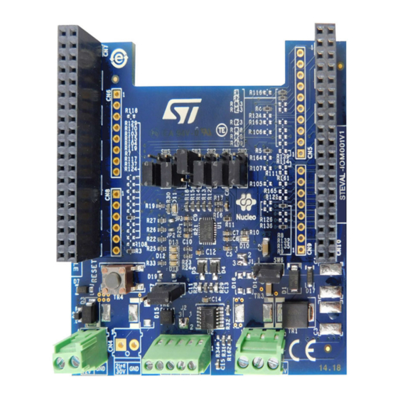
Figure 1.
UM2414 - Rev 2 - April 2021
For further information contact your local STMicroelectronics sales office.
P-NUCLEO-IOM01M1
STEVAL-IOM001V1 IO-Link physical master evaluation board
L6360
transceiver and is designed
NUCLEO-F446RE
development system, which includes a STEVAL-
UM2414
User manual
compatibility
or
NUCLEO-
www.st.com
Advertisement
Table of Contents

Related Manuals for ST UM2414


Summary of Contents for ST UM2414
-
Page 1: Figure 1. Steval-Iom001V1 Io-Link Physical Master Evaluation Board
STEVAL- IOM001V1 evaluation board and a NUCLEO-F446RE development board flashed with IO-Link stack (v1.1). Figure 1. STEVAL-IOM001V1 IO-Link physical master evaluation board UM2414 - Rev 2 - April 2021 www.st.com For further information contact your local STMicroelectronics sales office. -
Page 2: Hardware And Software Requirements
• a USB type A to mini-B USB cable to connect the STM32 Nucleo to the PC • STSW-IOM001 firmware and software package installed on the user PC • a 24 V power supply UM2414 - Rev 2 page 2/22... -
Page 3: Steval-Iom001V1 Evaluation Board Overview
• Ground and V wire break protections • EMC compliance with IEC61000-4-2, IEC61000-4-3, IEC61000-4-5 • Equipped with ST morpho connectors • CE certified • RoHS and China RoHS compliant Digital section The digital section is associated with the STM32 interface and the signals to control the... -
Page 4: Figure 3. Steval-Iom001V1 Expansion Board Digital Interface Components
UM2414 Digital section Figure 3. STEVAL-IOM001V1 expansion board digital interface components UM2414 - Rev 2 page 4/22... -
Page 5: St Morpho Connectors
The STEVAL-IOM001V1 communicates with the STM32 Nucleo board microcontroller and accesses the STM32 peripheral and GPIO resources through ST morpho connectors CN7 and CN10. These connectors also transfer digital supply voltages between the STM32 Nucleo development board and the STEVAL-IOM001V1 expansion board. -
Page 6: I2C Port Address
When multiple STEVAL-IOM001V1 evaluation boards are stacked, each board must be set with a different I2C address. You must set the I2C address in the I2C commands correctly for the SAx configuration of the L6360 to be controlled. UM2414 - Rev 2 page 6/22... -
Page 7: Reset Button
VDD pin of L6360 supplies 5.0V CLOSE 2-3 (default) VDD pin of L6360 supplies 3.3V CLOSE 1-2 (default) ENCQ pin of L6360 (U1) controlled by ENCQ signal. CLOSE 2-3 ENCQ pin of L6360 (U1) connected to VDD. UM2414 - Rev 2 page 7/22... -
Page 8: Io-Link Port Configuration
R165 CN10[26] 1. Modification is only required if OUTIQ is used. RELATED LINKS 2.2.1 ST morpho connectors on page 5 2.2.2 I2C Port address on page 6 2.2.5 SW3, SW4 and SW5 digital switches on page 7 Supply section The power to run the STEVAL-IOM001V1 evaluation board plus STM32 Nucleo development board can either be supplied through the mini-USB connector CN1 on the STM32 Nucleo (set JP5 on the U5V position) or through the STEVAL-IOM001V1 evaluation board. -
Page 9: Figure 4. Alternative Power Input Sections For The Steval-Iom001V1 Plus Stm32 Nucleo
UM2414 Supply section Figure 4. Alternative power input sections for the STEVAL-IOM001V1 plus STM32 Nucleo The VH pin on the L6360 can be supplied up to 32.5 V in the following ways: UM2414 - Rev 2 page 9/22... -
Page 10: Protection Features
Input pin for 2nd L+ power supply. Input pin for 2nd ground. Protection features The protection section implements reverse polarity protection and Electromagnetic compatibility (EMC) noise protection according to the industrial standards IEC61000-4-2 (ESD), IEC61000-4-4 (Burst) and IEC61000-4-5 (Surge). UM2414 - Rev 2 page 10/22... -
Page 11: Figure 5. Steval-Iom001V1 Expansion Board Power Section Components
L6360 pins VIN supply surge pulse suppressor Not mounted VIN Clamping for negative Surge Pulse protection Not mounted VIN reverse polarity protection diode Not mounted 2nd L+ supply surge pulse suppressor Not mounted UM2414 - Rev 2 page 11/22... -
Page 12: Powering And Initializing The Board
STM32 Nucleo microcontroller The firmware is the user reference code to control the L6360 and can be freely downloaded from www.st.com. You can use the STM32 ST-Link utility to load the firmware onto the STM32 Nucleo board. -
Page 13: Steval-Iom001V1 Schematic Diagrams
STEVAL-IOM001V1 schematic diagrams Figure 6. STEVAL-IOM001V1 circuit schematic (1 of 4) VCC_U1 VCC_U2 VCC_U2 VCC_U1 JUMP CQio CQio 100nF L+_U1 JUMP L+_ON L+_U1 NC12 D16 RED OUT11 L+_U2 L+_U2 DIAG OUT10 OUT9 OL-OFF OUT8 560pF 100nF IPS161H 560pF SPT01-335DEE C5 100nF YELLOW YELLOW LED2... -
Page 14: Figure 7. Steval-Iom001V1 Circuit Schematic (2 Of 4): Arduino Connectors
Figure 7. STEVAL-IOM001V1 circuit schematic (2 of 4): Arduino connectors 100R DEFAULT 100R DEFAULT AVDD R143 100R(N.M.) ENCQ 100R IOREF (PORT #1) ENL+ NRST R118 100R N.M. R163 100R(N.M.) (PORT #2) L+_ON R106 100R(N.M.) (PORT #1) OUTIQ R109 100R(N.M.) (PORT #4) OUTCQ DEFAULT 100R... -
Page 15: Figure 8. Steval-Iom001V1 Circuit Schematic (3 Of 4): St Morpho Connectors
Figure 8. STEVAL-IOM001V1 circuit schematic (3 of 4): ST morpho connectors (PORT #2) R116 100R(N.M.) OUTIQ CN10 SPI3_SCL PC10 PC11 SPI3_MISO 100R(N.M.) R133 ENCQ SPI3_MOSI PC12 PD2 SPI3_CS 100R(N.M.) R134 INCQ 100R(N.M.) R139 E5v0 OUTCQ BOOT0 AVDD PA12 IOREF 100R(N.M.) -
Page 16: Bill Of Materials
124kΩ 0.1W TE Connectivity CPF0603B124KE1 0.1% R12, R13, R14, 270Ω 0.1W R15, R16, R20, Vishay CRCW0603270RFKEA ±1% R21, R22 10kΩ 0.1W R17, R18, R31 TE Connectivity CRG0603F10K ±1% 3.3kΩ 0.1W TE Connectivity CRG0603F3K3 ±1% UM2414 - Rev 2 page 16/22... - Page 17 C1, C3 Vishay HV2220Y472KXHATHV Not mounted Vcc (VH) TVS surge SM15T33CA suppressor TR3, TR4 Not mounted VH TVS surge suppressor ST SM15T33CA IO-LINK LINE EMC SPT01-335DEE PROTECTION VCC reverse polarity STPS2L60A protection 2A, 60V VH reverse polarity 1A, Not mounted...
-
Page 18: Revision History
UM2414 Revision history Table 11. Document revision history Date Version Changes 04-Jun-2018 Initial release. 23-Apr-2021 Updated Section 3 STEVAL-IOM001V1 schematic diagrams. UM2414 - Rev 2 page 18/22... -
Page 19: Table Of Contents
ST morpho connectors ........ - Page 20 Figure 8. STEVAL-IOM001V1 circuit schematic (3 of 4): ST morpho connectors ......15 Figure 9.
- Page 21 Document revision history ............. 18 UM2414 - Rev 2...
- Page 22 ST’s terms and conditions of sale in place at the time of order acknowledgement. Purchasers are solely responsible for the choice, selection, and use of ST products and ST assumes no liability for application assistance or the design of Purchasers’...
Need help?
Do you have a question about the UM2414 and is the answer not in the manual?
Questions and answers