Advertisement
Quick Links
Advertisement

Subscribe to Our Youtube Channel
Related Manuals for DEFA Solid 712800


Summary of Contents for DEFA Solid 712800
- Page 1 EV Charging Station (EN) Installation manual...
-
Page 3: Table Of Contents
Table of Contents Safety information ....................Main parts ......................Installation planning .................... Installation ......................Testing and verification ..................Hand-over ......................Technical specification ..................Contact information .................... -
Page 4: Safety Information
NOTICE Sections marked with this symbol draw attention to additional important information and special features that are necessary for the reliable operation of the device. Actions marked with this symbol should be carried out as required. defa.com... - Page 5 Danger Do not install if the outer shell Do not install if the charging Do not carry out physical re- has been damaged. cable is defective or appears pairs on the charging station. cracked, broken or otherwise damaged. defa.com...
-
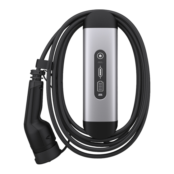
Page 6: Main Parts
B. Charging unit C. Display D. Charging cable E. Terminal block F. Rotary switch G. Wall bracket H. Spirit level Included J. 2 x end cap screws K.1 x fixing screw L. 4 x wall screws M. 4 x wall plugs defa.com... -
Page 7: Installation Planning
55mm Tools needed • Installation tools for correct wiring, including stripping tool. • Cross recessed screwdriver for wall bracket screws. • Torx tool size Tx 15 with space for safety pin. defa.com... -
Page 8: Installation
Attach the wall bracket. Use the built-in spirit level to ensure that the wall bracket is installed at a level angle. Use the four screws delivered with the product. The holes are made for screws with Ø4.2 mm. Remove the jacket (from A to B) with a length of 140 mm. Strip all single wires with 9-11 mm. defa.com... - Page 9 Place the cable in the groove that points the conductor toward the hole in the upper left corner. Slide the charging unit from the top, so that all the conductors fit into the cable entry in the inner end piece. Make sure that the grooves at the top and bottom are firmly in place. defa.com...
- Page 10 Attach the fixing screw to secure the charging unit to the wall bracket. defa.com...
- Page 11 Insert the conductors L, N and PE (earth) into the terminal block (see image below), and check that they are all firmly attached. NOTICE If the PE conductor is not isolated, add an insulation tube or electrical tape in the exposed area. 12. Place the cable in the position shown in the image below. defa.com...
- Page 12 Set the required charging level. 14. Attach a sticker with the set rating - max charging power - on the underside of the vehicle plug (over the existing rating label). defa.com...
- Page 13 15 A 3,5 kW 13 A 13 A 3,0 kW 10 A 10 A 2,3 kW 1,8 kW 1,4 kW 15. Attach outer end cap with two screws on top of the charging unit to close the installation area. defa.com...
- Page 14 16. Coil charging cable around the charging unit. 17. Turn the power/fuse on. defa.com...
-
Page 15: Testing And Verification
Make sure the charging station is ready to use by checking which signals are displayed on the display before, during, and after charging the vehicle. See chapter Charge the vehicle in the user manual. Display view A. Power Input Indication B. Select Button C. Charger Status Indication D. Vehicle Connection Indication defa.com... -
Page 16: Hand-Over
• Show which rating the installation has. • Demonstrate how to use the device. • Inform how to find further information about their device • Inform what to do if they experience issues with their device. • Hand over the user manual. defa.com... -
Page 17: Technical Specification
Storage temperature -50 °C to +85 °C Size (L x W x T) 312 x 85 x 70 mm Material charging unit Aluminum IK rating IK 08 IP rating IP 44 Weight 2,3 kg Certification CE, IEC61851, IEC62955 Recycling EE-waste defa.com... -
Page 18: Contact Information
Contact information If you have any questions, contact your local vendor, visit defa.com or call DEFA support: • Phone (Norway/International): +47 32 06 77 00 • Phone (Sweden/International): +46 10 498 38 00 • Phone (Finland): +358 (0)20 152 72 00 If you have any feedback on how the system or support can be improved, feel free to give us your input at connect@defa.com...
Need help?
Do you have a question about the Solid 712800 and is the answer not in the manual?
Questions and answers