Advertisement
Quick Links
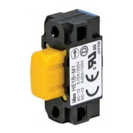
HE1B Key features include:
• 3 position funtionality (OFF – ON –OFF) as required for manual robotic control
• Ideally suited for use as enabling (aka "deadman") switch on teach pendants
• Provides a high level of safety based on human behavioral studies that determine
personnel may squeeze OR let go when presented with a panic situation
• Positive action contacts "On" (pos. 2) to "Off" (pos. 3) ensure no contact welding (per
EN60947-5-1 / IEC60947-5-1)
• Contacts will not close when released from "Off" (pos. 3) to "Off" (pos. 1)
(per IEC60204-1; 9.2.5.8)
• Small, lightweight and highly reliable
Specifications
Conforming to Standards
Operating Temperature
Operating Humidity
Storage Temperature
Pollution Degree
Initial Contact Resistance
Insulation Resistance
Impulse Withstand Voltage
Operating Frequency
Mechanical Life
Electrical Life
Operating Extremes
Shock Resistance
Damage Limits
Operating Extremes
Vibration Resistance
Damage Limits
Terminal Shape
Recommended Wire
Solder Heat Resistance
Terminal Pulling Strength
Recommended Screw Torque
Degree of Protection
Conditional Short-Circuit Current
Recommended Short Circuit Protection
Weight
Circuit Opening Force
Control Resistance (Operating)
Phone: 800.894.0412 - Fax: 888.723.4773 - Web: www.clrwtr.com - Email: info@clrwtr.com
HE1B Series Basic Enabling Switch
IEC60947-5-1, EN60947-5-1, JIS C8201-5-1, UL508, CSA C22.2 No 14
–25 to +60˚C (no freezing)
45 to 85% RH maximum (no condensation)
–40 to +80˚C (no freezing)
2
50mΩ maximum
100MΩ minimum
2.5kV
1200 operations/hour
Position 1‡2: 1,000,000 operations minimum
Position 1‡2‡3‡1: 100,000 operations minimum
100,000 operations minimum at rated load
100m/s
(10G)
2
1000m/s
(100G)
2
5 to 55Hz, amplitude 0.5mm minimum
16.7Hz, amplitude 1.5mm minimum
Solder Terminal
0.5mm
maximum / 1 line (20AWG)
2
260°C / 3 seconds maximum
20N minimum
HE1B-M1: M3 screw / 0.5 to 0.8Nm
IP40 (IEC 60529) excluding terminal part
50A (250V)
250V, 10A fast blow fuse (IEC 60127-1)
Approx. 6g
30N minimum (position 2‡3)
250N minimum
Advertisement

Related Manuals for IDEC HE1B Series


Summary of Contents for IDEC HE1B Series
- Page 1 HE1B Series Basic Enabling Switch HE1B Key features include: • 3 position funtionality (OFF – ON –OFF) as required for manual robotic control • Ideally suited for use as enabling (aka “deadman”) switch on teach pendants • Provides a high level of safety based on human behavioral studies that determine personnel may squeeze OR let go when presented with a panic situation •...
- Page 2 Enabling Switches HE1B Series Part Numbers Item Installation Part Number Side HE1B-M1 Front HE1B-M1N Current Ratings Rated Insulation Voltage (Ui) AC / DC250V Thermal Current (lth) Rated Operating Voltage (Ue) 125V 250V Resistive Load (AC-12) – 1.5A AC 50/60Hz Inductive Load (AC-15) –...
- Page 3 Dimensions (mm) When pressed to position 3: 2 13.6 Solder Terminal Installation Dimensions (mm) HE1B-M1 (Side Mounting) HE1B-M1N (Front Mounting) 1. M3 Screw (not provided) 1. M3 Screw (not provided) 2. Thread built in 2. Locking nut (2 pcs) included 15 min.
- Page 4 Enabling Switches General Information General Information Safety Precautions • In order to avoid electric shock or fire, turn power off before installation, • Use proper wire diameter to meet voltage and current requirements. Using removal, wire connection, maintenance or inspection of switch. improper wires or incomplete soldering may cause fire due to abnormal heat generation.