Table of Contents
Advertisement
Quick Links
SERVICE & OPERATING MANUAL
Original Instructions
Certified Quality
ISO 9001 Certified
ISO 14001 Certified
Warren Rupp, Inc.
A Unit of IDEX Corporation
800 N. Main St.,
Mansfield, Ohio 44902 USA
Telephone 419.524.8388
Fax 419.522.7867
SANDPIPERPUMP.COM
© Copyright 2017 Warren Rupp, Inc.
All rights reserved
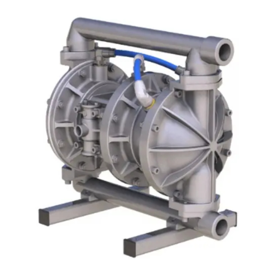
Model HP10
Metallic - High Pressure
Design Level 1
s a n d p i p e r p u m p. c o m
Advertisement
Table of Contents

Related Manuals for Warren rupp SANDPIPER HP10


Summary of Contents for Warren rupp SANDPIPER HP10
- Page 1 A Unit of IDEX Corporation 800 N. Main St., Mansfield, Ohio 44902 USA Telephone 419.524.8388 Fax 419.522.7867 SANDPIPERPUMP.COM © Copyright 2017 Warren Rupp, Inc. All rights reserved s a n d p i p e r p u m p. c o m...
- Page 2 The use of non-OEM replacement parts will void (or negate) agency certifications, including CE, ATEX, CSA, 3A and EC1935 compliance (Food Contact Materials). Warren Rupp, Inc. cannot ensure nor warrant non-OEM parts to meet the stringent requirements of the certifying agencies.
- Page 3 Temperature Tables Table 1. Category 1 & Category 2 ATEX Rated Pumps Ambient Temperature Process Temperature Temperature Maximum Surface Tem- Range [°C] Range [°C] Class perature [°C] -20°C to +80°C T100°C -20°C to +108°C T135°C -20°C to +60°C -20°C to + 160°C T200°C -20°C to +177°C (225°C) T2 Per CSA standards ANSI LC6-2018 US & Canadian Technical Letter R14, G-Series Natural Gas Models are restricted to (-20°C to + 80°C) process temperature Table 2. Category 2 ATEX Rated Pumps Equipped with Pulse Output Kit or Integral Solenoid: Options Ambient Temperature Process Temperature...
-
Page 4: Table Of Contents
Table of Contents SECTION 1: PUMP SPECIFICATIONS ....1 • Explanation of Nomenclature • Performance • Materials • Dimensional Drawings SECTION 2: INSTALLATION & OPERATION ...5 • Principle of Pump Operation • Recommended Installation Guide • Troubleshooting Guide SECTION 3: EXPLODED VIEW ......8 •... -
Page 5: Explanation Of Nomenclature
Explanation of Pump Nomenclature Your Model #: ____ ____ (fill in from pump nameplate) Pump Pump Check Design Wetted Diaphragm/ Check Valve Non-Wetted Porting Pump Pump Brand Size Valve Level Material Check Valve Seat Material Options Style Options Options Model #: Pump Brand Check Valve Seat HP SANDPIPER... -
Page 6: Performance
Performance HP10 HIGH PRESSURE SUCTION/DISCHARGE PORT SIZE MODEL HP10 Performance Curve • 1" NPT (internal) Performance based on the following: elastomer fitted pump, flooded suction, water at ambient conditions. The use of other materials and varying hydraulic AIR CONSUMPTION • 1" BSP Tapered (internal) conditions may result in deviations in excess of 5%. -
Page 7: Dimensional Drawings
Dimensional Drawings HP10 High Pressure Dimensions in inches (mm dimensions in brackets). Dimensional Tolerance:±1/8" (± 3mm) The dimensions on this drawing are for reference only. A certified drawing can be requested if physical dimensions are needed. HP10 SANDPIPER HIGH PRESSURE PUMP ALL DIMENSIONS +/- 1/8"... -
Page 8: Principle Of Pump Operation
Principle of Pump Operation Air-Operated Double Diaphragm (AODD) pumps are powered by compressed air or nitrogen. The main directional (air) control valve distributes ① compressed air to an air chamber, exerting uniform pressure over the inner surface of the diaphragm . -
Page 9: Recommended Installation Guide
Recommended Installation Guide Available Accessories: 1. Surge Suppressor Unregulated Air Supply to Surge 2. Filter/Regulator Suppressor 1 Surge Suppressor 3. Air Dryer 4. Lubricator Pressure Gauge Note: Surge Suppressor and Shut-Off Valve Piping, including air line, must be supported after the flexible connections. Pipe Connection (Style Optional) Discharge... -
Page 10: Troubleshooting Guide
Troubleshooting Guide Symptom: Potential Cause(s): Recommendation(s): Pump Cycles Once Deadhead (system pressure meets or exceeds air Increase the inlet air pressure to the pump. Pump is designed for 1:1 pressure ratio at zero flow. supply pressure). (Does not apply to high pressure 2:1 units). Air valve or intermediate gaskets installed incorrectly. -
Page 11: Composite Repair Parts Drawing
Composite Repair Parts Drawing OVERLAY OPTION WET SIDE EXPLODED ASSEMBLY *optional ground strap available for purchase separately TORQUE SETTINGS Service & Repair Kits WET SIDE SERVICE KITS 476.391.360 WET END KIT - BUNA Buna Diaphragms, Buna Check Balls, Buna O-Rings 476.391.365 WET END KIT - NEOPRENE Neoprene Diaphragms, Neoprene Check Balls, Neoprene O-Rings 476.391.635 Wet End Kit - PTFE PTFE Diaphragms, Neoprene Backup Diaphragms, PTFE Check Balls, FEP O-Rings 476.391.644 Wet End Kit - SANTOPRENE/PTFE Santoprene Diaphragms, PTFE Check Balls, EPDM O-Rings sandpiperpump Model HP10 High Pressure •... - Page 12 Composite Repair Parts Drawing AIR SIDE EXPLODED ASSEMBLY TORQUE SETTINGS Service & Repair Kits 476.392.000 AIR END KIT Air Side Diaphragm, Air Hoses, Seals and O-rings sandpiperpump • Model HP10 High Pressure hp10mdl1sm-rev0521...
- Page 13 Composite Repair Parts List Item Part Number Description Item Part Number Description 40-240 Muffler, Exhaust 1A007 Plate, Inner Diaphragm 40-259 Block, Center 1A009 Bumper 40-265 Body, Air Valve NPT 1A072 Ball, Check Weighted - Buna 40-264 Body, Air Valve BSP 1A091 Ball, Check Weighted - Neoprene 40-266...
- Page 14 TECHNICAL NOTES :- Removal of Diaphragm Shaft :- After first removing manifolds and air-hoses, remove both outer covers (13), followed by frontplates (12), fluid diaphragms (11), backplates (9) and bumpstops (8 & 24). Separate Spacer/Covers Assy. from Valve Chest Assy. by removing 8 off M8 x 35 bolts and sliding either halve from shaft.
- Page 15 TECHNICAL NOTES :- 25-111 25-085 25-110 Valve Block on left. Spacer Covers on right. Air Hose connections :- When looking from the air valve side of the pump, air hoses (items 19 & 20) are connected as shown. Inner chamber LH (22) connects to LH spacer chamber (21) and inner chamber RH (10) connects to RH spacer chamber (21).
- Page 16 IMPORTANT! the valve system to malfunction. R E P L A C I N G D I A P H R A G M S Remove both suction and discharge Read these instructions Re-assemble valve block manifolds as detailed in the previous c o m p l e t e l y , b e f o r e assembly &...
- Page 17 Warren Rupp, Inc. (“Warren Rupp”) warrants to the original end-use purchaser that no product sold by Warren Rupp that bears a Warren Rupp brand shall fail under normal use and service due to a defect in material or workmanship within five years from the date of shipment from Warren Rupp’s factory.
- Page 18 A Unit of IDEX Corporation 800 North Main Street Mansfield, OH 44902 USA Warren Rupp, Inc. declares that Air Operated Double Diaphragm Pumps (AODD) and Surge Suppressors listed below comply with the requirements of Directive 2014/34/EU and all applicable standards. Applicable Standards •...
Need help?
Do you have a question about the SANDPIPER HP10 and is the answer not in the manual?
Questions and answers