Advertisement
Quick Links
Description
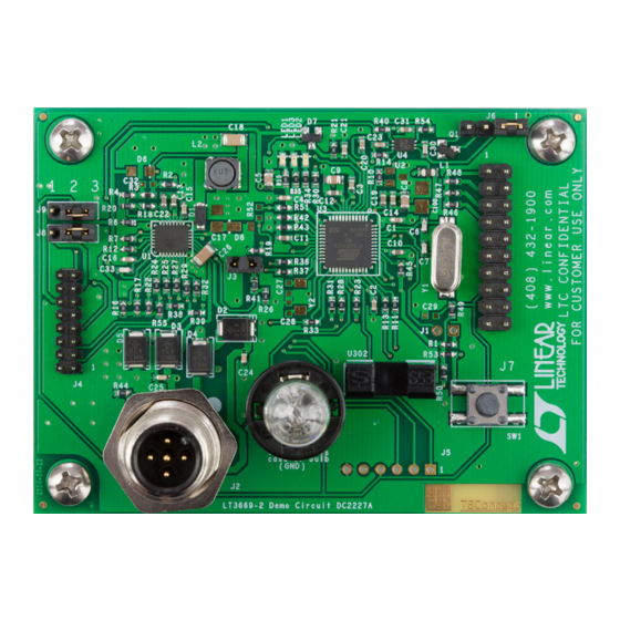
Demonstration circuit 2227A is a complete IO-Link
vice built using the
LT
3669-2
®
v1.1 physical interface (PHY). The IO-Link stack protocol
runs on an Atmel ATmega microcontroller which connects
to LT3669-2's logic IO-signals to communicate with an
IO-Link master via the CQ1 transceiver.
An LTC2997 temperature sensor, an opto-coupler (light
barrier) and a pushbutton demonstrate IO-Link device
functionality and master-slave interoperability.
performance summary
SYMBOL
PARAMETER
L+
Input Supply
V
LT3669-2's Buck Output Voltage
BUCK
V
LT3669-2's LDO Output Voltage
LDO
BoarD photo
IO-Link Device with Multiple Sensors
de-
®
to implement an IO-Link
Specifications are at T
CONDITIONS
DEMO MANUAL DC2227A
A 28V/100mA light bulb connected to LT3669-2's second
driver (Q2) demonstrates its high current driving capabili-
ties. All low voltage circuitry is supplied by the LT3669-2's
integrated buck and LDO for high efficiency.
Design files for this circuit board are available at
http://www.linear.com/demo/DC2227A
L, LT, LTC, LTM, Linear Technology and the Linear logo are registered trademarks of Linear
Technology Corporation. IO-Link is a registered trademark of PROFIBUS User Organization
(PNO). All other trademarks are the property of their respective owners.
= 25°C, V
+ = 24V
A
L
LT3669-2
MIN
TYP
MAX
18
36
3.8
4
4.2
3.135
3.3
3.465
dc2227af
UNITS
V
V
V
1
Advertisement

Subscribe to Our Youtube Channel
Related Manuals for Linear Technology LT3669-2


Summary of Contents for Linear Technology LT3669-2
- Page 1 An LTC2997 temperature sensor, an opto-coupler (light L, LT, LTC, LTM, Linear Technology and the Linear logo are registered trademarks of Linear barrier) and a pushbutton demonstrate IO-Link device Technology Corporation. IO-Link is a registered trademark of PROFIBUS User Organization (PNO).
-
Page 2: Quick Start Procedure
DEMO MANUAL DC2227A Quick start proceDure Additional Hardware and Software Requirements Operation in COM2 To operate the DC2227A demo circuit in IO-Link mode, 7. Click on the “Select Device” button again, this time additional hardware and software are required: making sure the correct port is selected. Use the fol- lowing IODD file: • PC running Windows XP or later with Ethernet Card. - Page 3 DEMO MANUAL DC2227A Quick start proceDure Figure 1. Recommended Set-up for Operating DC2227A in IO-Link Mode Figure 2. Control Tool for Connecting DC2227A to DC2228A dc2227af...
-
Page 4: Additional Information
1.8V reference voltage (V ) and the by the pulsing mechanism of the LT3669-2. To prevent data VPTAT outputs of the LTC2997 to report the temperature loss in IO-Link mode, driver Q2 is only enabled in between in Celsius to the IO-Link master. - Page 5 Connectors and Jumpers Jumper J3 The board has the following connectors: Jumper J3 enables/disables the on board LT3669-2 (which also generates the internal 3.3V supply rail). Close this Table 1. Connectors and Jumpers Overview jumper (default position) to use the onboard LT3669-2...
- Page 6 Close 1-2 to Use DC1733A-B as PHY Function Comment Local VDD3 rail Default: Connected to Pin 3 MISO Master In Slave Out Local LT3669-2’s LDO Close 2-3 to Use Local LT3669-2 as PHY MOSI Master Out Slave In Jumper J9 SPCK SPI Clock RESETn Reset J9 selects the source for the microcontroller’s reset pin.
- Page 7 DEMO MANUAL DC2227A aDDitional information IO Device Description IODD File (COM2): TEConcept_GmbH-65538-<YYYYMMDD>-IODD1.1 IODD File (COM3): TEConcept_GmbH-65539-<YYYYMMDD>-IODD1.1 Release Date: <YYYY-MM-DD> Release Date: <YYYY-MM-DD> Document Version: V1.0 Document Version: V1.0 Device ID: 65538 Device ID: 65539 Bit Rate: COM2 Bit Rate: COM3 IO-Link Version: 1.1 IO-Link Version: 1.1 MinCycleTime: 20ms...
- Page 8 DEMO MANUAL DC2227A aDDitional information Variables Name Description Index Subindex Datatype Length Access Rights Default Value Range Unit System Command Command Code UIntegerT 8 Bit Definition Device Access Standardized Device RecordT 1 Bit Locks Locking Functions Parameter (Write) Parameter Write BooleanT 1 Bit 0 or 1...
-
Page 9: Parts List
DEMO MANUAL DC2227A parts list ITEM REFERENCE PART DESCRIPTION MANUFACTURER/PART NUMBER Required Circuit Components C1, C2, C3, C4, C14, C16 CAP, X5R, 100nF, 10%, 10V, 0603 AVX, 0603ZD104KAT2A C5, C8, C9 CAP, X5R, 4.7µF, 10%, 10V, 0805 MURATA, GRM21BR71A475KA73L C6, C7 CAP, NP0, 18pF, 10%, 25V, 0603 AVX, 06033A180KAT2A C10, C11, C12, C13, C22... - Page 10 DEMO MANUAL DC2227A parts list ITEM REFERENCE PART DESCRIPTION MANUFACTURER/PART NUMBER Push-Buttom Specific Components RES, 4.7k, 1%, 1/10W, 0603 VISHAY, CRCW06034K70FKEA SWITCH, PUSHBUTTON WÜRTH ELEKTRONIK, 430182050816 Additional Demo Board Circuit Components: CAP, X5R, 100nF, 10%, 10V, 0603 AVX, 0603ZD104KAT2A OPTIONAL C27, C28, C29, C32 OPTIONAL C100...
-
Page 11: Schematic Diagram
Information furnished by Linear Technology Corporation is believed to be accurate and reliable. However, no responsibility is assumed for its use. Linear Technology Corporation makes no representa- tion that the interconnection of its circuits as described herein will not infringe on existing patent rights. - Page 12 Linear Technology Corporation (LTC) provides the enclosed product(s) under the following AS IS conditions: This demonstration board (DEMO BOARD) kit being sold or provided by Linear Technology is intended for use for ENGINEERING DEVELOPMENT OR EVALUATION PURPOSES ONLY and is not provided by LTC for commercial use. As such, the DEMO BOARD herein may not be complete in terms of required design-, marketing-, and/or manufacturing-related protective considerations, including but not limited to product safety measures typically found in finished commercial goods.
- Page 13 Mouser Electronics Authorized Distributor Click to View Pricing, Inventory, Delivery & Lifecycle Information: Analog Devices Inc. DC2227A...
Need help?
Do you have a question about the LT3669-2 and is the answer not in the manual?
Questions and answers