Advertisement
Quick Links
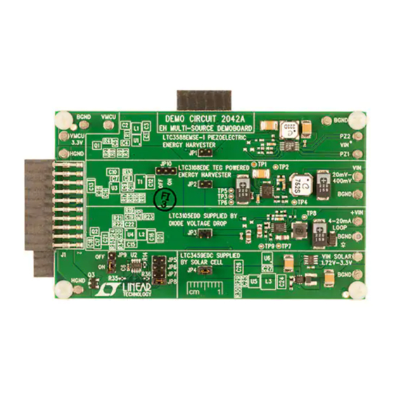
DESCRIPTION
The
DC2042A
is a versatile energy harvesting demo board
that is capable of accepting piezoelectric, solar, 4mA to
20mA loops, thermal-powered energy sources or any high
impedance AC or DC source. The board contains four
independent circuits consisting of the following EH ICs:
•
LTC
3588-1: Piezoelectric Energy Harvesting Power
®
Supply.
• LTC3108: Ultralow Voltage Step-Up Converter and
Power Manager.
• LTC3105: Step-Up DC/DC Converter with Power Point
Control and LDO Regulator.
• LTC3459: 10V Micropower Synchronous Boost
Converter.
• LTC2935-2/LTC2935-4: Ultralow Power Supervisor
with Power-Fail Output Selectable Thresholds.
The board supports the following interconnects:
• Direct connection with the Dust Mote demo boards, the
DC9003A-B Mote on a chip or the DC9003A-A Manager
on a chip.
• Energy Micro STK development kit.
Energy Harvesting (EH) Multisource
DC2042A Connected to DC9003A-B Dust Mote (Top View)
DEMO MANUAL DC2042A
LTC3588-1/LTC3108/LTC3105/
LTC3459/LTC2935-2/LTC2935-4
In addition, many turrets are provided and one transducer
header is available to make it easy to connect transducers
to the board.
The board contains multiple jumpers that allow the board
to be configured in various ways. The standard build for
the board has three jumpers installed out of the possible
10 jumpers. The board is very customizable to the end
users' needs. This compatibility makes it a perfect evalu-
ation tool for any low power energy harvesting system
Please refer to the individual data sheets for the opera-
tion of each power management circuit. The application
section of this demo manual describes the system level
functionality of this board and the various ways it can be
used in early design prototyping.
Design files for this circuit board are available at
http://www.linear.com/demo
L, LT, LTC, LTM, Linear Technology and the Linear logo are registered trademarks of Linear
Technology Corporation. All other trademarks are the property of their respective owners.
Demo Board
dc2042af
1
Advertisement


Need help?
Do you have a question about the LTC3588-1 and is the answer not in the manual?
Questions and answers