Advertisement
Quick Links
DESCRIPTION
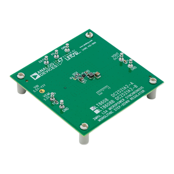
Demonstration circuit 2521A is a 42V, 1.5A micropower
synchronous step-down regulator featuring the
LT8608B. There are two assembly versions. DC2521A-A
is for the LT8608 and DC2521A-B is for the LT8608B.
The LT8608/LT8608B is a compact, high efficiency, high
speed synchronous monolithic step-down switching
regulator. Top and bottom power switches, compensa-
tion components and other necessary circuits are inside
of the 2mm × 2mm DFN package to minimize external
components and simplify design. The difference LT8608
and LT8608B is the LT8608 works under low ripple
Burst Mode
operation at light load condition, while the
®
LT8608B has pulse-skipping mode for light load. Due
to the Burst Mode operation, LT8608 consumes only
1.7μA of quiescent current when output is regulated at
5V. LT8608B has higher quiescent current because of its
pulse-skipping mode operation.
PERFORMANCE SUMMARY
SYMBOL
PARAMETER
V
Input Voltage Range
IN
V
Output Voltage
OUT
I
Maximum Output Current
OUT
f
Switching Frequency
SW
EFE
Efficiency at DC
DEMO MANUAL DC2521A
Synchronous Step-Down Regulator
The demo board is designed for 5V output from a 5.5V
LT8608/
to 42V input. The wide input range allows a variety of
input sources, such as automotive batteries and industrial
supplies.
The demo board has an EMI filter installed. The radiated
EMI performances of the board (with EMI filter) are shown
in Figure 2 and Figure 3. The red lines in Figure 2 and
Figure 3 are CISPR 25 Class 5 peak limit. To use the EMI
filter, the input should be tied to V
tor L2, which is a 0Ω jumper on the board by default
now, can be added in the EMI filter to further reduce the
conducted emission.
The LT8608 data sheet gives a complete description of
the part, operation and application information. The data
sheet must be read in conjunction with this demo manual
for DC2521A.
Design files for this circuit board are available.
All registered trademarks and trademarks are the property of their respective owners.
Specifications are at T
CONDITIONS
V
= 12V, I
= 0.75A
IN
OUT
LT8608/LT8608B
42V, 1.5A Micropower
= 25°C
A
MIN
TYP
5.5
4.8
5
1.5
1.85
2
92
, not V
. An induc-
EMI
IN
MAX
UNITS
42
V
5.2
V
A
2.15
MHz
%
UG-1403 Rev. 0
1
Advertisement

Subscribe to Our Youtube Channel
Related Manuals for Linear Technology Analog Devices LT8608B


Summary of Contents for Linear Technology Analog Devices LT8608B
- Page 1 DEMO MANUAL DC2521A LT8608/LT8608B 42V, 1.5A Micropower Synchronous Step-Down Regulator DESCRIPTION Demonstration circuit 2521A is a 42V, 1.5A micropower The demo board is designed for 5V output from a 5.5V synchronous step-down regulator featuring the LT8608/ to 42V input. The wide input range allows a variety of LT8608B.
- Page 2 DEMO MANUAL DC2521A QUICK START PROCEDURE DC2521A is easy to set up to evaluate the performance 5. Once the proper output voltage is established, connect of the LT8608/LT8608B. Refer to Figure 4 for proper a variable load capable of sinking 1.5A at 5V to the measurement equipment setup and follow the proce- output terminals V and GND.
-
Page 3: Quick Start Procedure
DEMO MANUAL DC2521A QUICK START PROCEDURE Figure 4. Proper Measurement Equipment Setup Figure 5. Measuring Output Ripple UG-1403 Rev. 0... -
Page 4: Parts List
DEMO MANUAL DC2521A PARTS LIST ITEM REFERENCE PART DESCRIPTION MANUFACTURER/PART NUMBER Required Circuit Components CAP ., X7R, 4.7μF, 50V, 10% 1206 MURATA, GRM31CR71H475K CAP ., X7R, 0.22μF, 16V, 10%, 0603 AVX, 0603YC224KAT2A CAP ., C0G, 10pF, 25V, 5%, 0603 AVX, 06033A100JAT2A CAP ., X7R, 47μF, 10V, 10%, 1210 MURATA, GRM32ER71A476KE20L CAP ., X7R, 1.0μF, 25V, 10%, 0603... -
Page 5: Schematic Diagram
DEMO MANUAL DC2521A SCHEMATIC DIAGRAM UG-1403 Rev. 0 Information furnished by Analog Devices is believed to be accurate and reliable. However, no responsibility is assumed by Analog Devices for its use, nor for any infringements of patents or other rights of third parties that may result from its use. Specifications subject to change without notice. - Page 6 DEMO MANUAL DC2521A ESD Caution ESD (electrostatic discharge) sensitive device. Charged devices and circuit boards can discharge without detection. Although this product features patented or proprietary protection circuitry, damage may occur on devices subjected to high energy ESD. Therefore, proper ESD precautions should be taken to avoid performance degradation or loss of functionality. Legal Terms and Conditions By using the evaluation board discussed herein (together with any tools, components documentation or support materials, the “Evaluation Board”), you are agreeing to be bound by the terms and conditions set forth below (“Agreement”) unless you have purchased the Evaluation Board, in which case the Analog Devices Standard Terms and Conditions of Sale shall govern.
Need help?
Do you have a question about the Analog Devices LT8608B and is the answer not in the manual?
Questions and answers