
Related Manuals for Contec PIO-32DM


Summary of Contents for Contec PIO-32DM
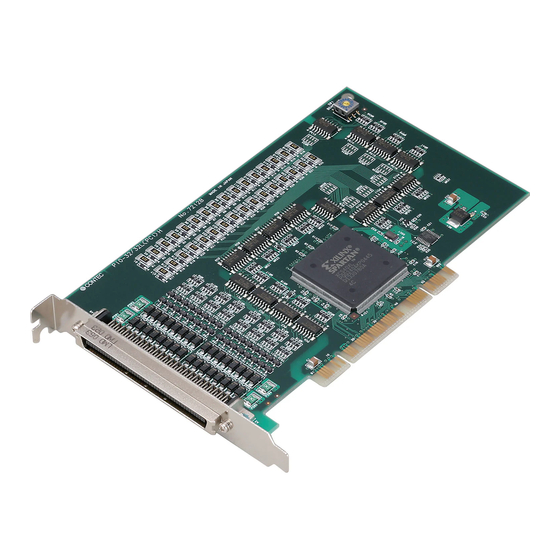
- Page 1 High Speed Bi-Directional Digital I/O Board for PCI PIO-32DM(PCI) User’s Guide CONTEC CO.,LTD.
- Page 2 Check Your Package Thank you for purchasing the CONTEC product. The product consists of the items listed below. Check, with the following list, that your package is complete. If you discover damaged or missing items, contact your retailer. Product Configuration List - Board [PIO-32DM(PCI)] …1...
-
Page 3: Copyright
No part of this document may be copied or reproduced in any form by any means without prior written consent of CONTEC CO., LTD. CONTEC CO., LTD. makes no commitment to update or keep current the information contained in this document. The information in this document is subject to change without notice. -
Page 4: Table Of Contents
When Using API-DIO(WDM)......................11 When Using API-DIO(98/PC) ......................12 Step 2 Setting the Hardware ......................... 14 Parts of the Board and Factory Defaults ..................14 Setting the Board ID ........................15 Plugging the Board......................... 16 Step 3 Installing the Hardware ......................17 PIO-32DM(PCI) - Page 5 Connecting the SC Connectors (CN2,CN3) ..................42 FUNCTION Function Outline ............................43 Overview............................43 Sampling function / generating function ..................43 Bus Master Transfer ........................43 Interrupt (at the time of bus master transfer).................44 Status, count............................44 Sampling function..........................45 Sampling control..........................45 Generating function ..........................46 Generating control ..........................46 PIO-32DM(PCI)
- Page 6 Uninstalling the Driver Libraries ....................54 About Software for Linux ........................55 Driver Software Install Procedure ....................55 Accessing the Help File ......................... 56 Using Sample Programs......................... 56 Uninstalling the driver ........................56 ABOUT HARDWARE Hardware specification ......................... 57 Block Diagram ............................59 PIO-32DM(PCI)
- Page 7 PIO-32DM(PCI)
-
Page 8: Before Using The Product
This chapter provides information you should know before using the product. About the Board The PIO-32DM(PCI) is an interface board in compliance with the PCI bus specification and performs high-speed digital input and output application using bus mastering. This should be installed in a PCI bus slot. -
Page 9: Support Software
Visual Basic, Visual C++, Visual C#, Delphi, C++ Builder You can download the updated version from the CONTEC’s Web site (http://www.contec.com/apipac/). For more details on the supported OS, applicable language and new information, please visit the CONTEC’s Web site. Linux version of digital I/O driver API-DIO(LNX) -
Page 10: Customer Support
You can download updated driver software and differential files as well as sample programs available in several languages. Note! For product information Contact your retailer if you have any technical question about a CONTEC product or need its price, delivery time, or estimate information. Limited Three-Years Warranty CONTEC Interface products are warranted by CONTEC CO., LTD. -
Page 11: Safety Precautions
WARNING indicates a potentially hazardous situation which, if not avoided, could result in death or serious injury. CAUTION indicates a potentially hazardous situation which, if not avoided, may result in minor or moderate injury or in property damage. PIO-32DM(PCI) -
Page 12: Handling Precautions
Even when using the product continuously, be sure to read the user’s guide and understand the contents. Do not modify the product. CONTEC will bear no responsibility for any problems, etc., resulting from modifying this product. Regardless of the foregoing statements, CONTEC is not liable for any damages whatsoever (including damages for loss of business profits) arising out of the use or inability to use this CONTEC product or the information contained herein. -
Page 13: Environment
(3) Store the package at room temperature at a place free from direct sunlight, moisture, shock, vibration, magnetism, and static electricity. Disposal When disposing of the product, follow the disposal procedures stipulated under the relevant laws and municipal ordinances. PIO-32DM(PCI) -
Page 14: Setup
For setting up software other than API-PAC(W32), refer to the user’s guide for that software. See also the following parts of this user’s guide as required. This chapter Step 2 Setting the Hardware This chapter Step 3 Installing the Hardware Chapter 3 External Connection Chapter 6 About Hardware PIO-32DM(PCI) -
Page 15: Using The Board Under An Os Other Than Windows
Using the Board under an OS Other than Windows For using the board under an OS other than Windows, see the following parts of this user’s guide. This chapter Step 2 Setting the Hardware Chapter 3 External Connection Chapter 6 About Hardware PIO-32DM(PCI) -
Page 16: Step 1 Installing The Software
OS and devices in the future but will not support Windows NT 4.0, Windows 95, ISA bus. Use API-DIO(98/PC) if your operating environment contains such an unsupported piece of software or hardware. Check the following selection guide to easily select the driver to be used. PIO-32DM(PCI) -
Page 17: Starting The Install Program
(3) Click on the [Install Development or Execution Environment] button. When using the Windows Vista, driver is automatically installed. Before installing the software in Windows Vista, XP, Server 2003 and 2000, log in as a user with administrator privileges. PIO-32DM(PCI) -
Page 18: When Using Api-Dio(Wdm)
(3) Click on the [Install] button. Clicking the [API-DIO] button displays detailed information about API-DIO(WDM) and API-DIO(98/PC). Run the installation (1) Complete the installation by following the instructions on the screen. (2) The Readme file appears when the installation is complete. PIO-32DM(PCI) -
Page 19: When Using Api-Dio(98/Pc)
(1) The following dialog box appears to select “Driver to install” and “Install option”, “Usage of driver library”. (2) Select “Classic Digital I/O driver”. (3) Click on the [Install] button. Clicking on the [API-DIO] button displays detailed information on API-DIO(WDM), API-DIO(98/PC). PIO-32DM(PCI) - Page 20 Go to Step 2 to set and plug the hardware. * When the hardware has already been installed: Check “Perform a hardware setup now(API-TOOL Configuration)”, then go to Step 4 “Initializing the Software”. You have now finished installing the software. PIO-32DM(PCI)
-
Page 21: Step 2 Setting The Hardware
The board can be set up even with the factory defaults untouched. You can change board settings later. Parts of the Board and Factory Defaults Figure 2.1. shows the names of major parts on the board. Note that the switch setting shown below is the factory default. Figure 2.1. Component Locations PIO-32DM(PCI) -
Page 22: Setting The Board Id
If only one board is used, the original factory setting (Board ID = 0) should be used. Setting Procedure To set the board ID, use the rotary switch on the board. Turn the SW1 knob to set the board ID as shown below. Figure 2.2. Board ID Settings (SW1) PIO-32DM(PCI) -
Page 23: Plugging The Board
Be sure that the personal computer power is turned off. Make sure that your PC or expansion unit can supply ample power to all the boards installed. Insufficiently energized boards could malfunction, overheat, or cause a failure. Power supply from the PCI bus slot at +5V is required. PIO-32DM(PCI) -
Page 24: Step 3 Installing The Hardware
In this case, you must check the resource settings. When Using API-DIO(WDM) (1) The “Found New Hardware Wizard” will be started. Select “No, not this time” and then click the “Next” button. PIO-32DM(PCI) - Page 25 When the model name of hardware is displayed, select “Install the software automatically [Recommended]” and then click on the “Next” button. Source folder The setup information (INF) file is contained in the following folder on the bundled CD-ROM. Windows Vista, XP, Server 2003, 2000 \INF\Wdm\Dio \INF\Wdm\Dio PIO-32DM(PCI)
- Page 26 2. Setup * The name of the board you have just added is displayed. - PIO-32DM(PCI) You have now finished installing the hardware. PIO-32DM(PCI)
-
Page 27: When Using Api-Dio(98/Pc)
If you are using Windows NT 4.0, the “Add New Hardware Wizard” is not started. Go to Step 4 “Initializing the Software”. Select “No, not this time” and then click the “Next” button. (2) Select “Install from a list or specific location[Advanced]” and then click the “Next” button. PIO-32DM(PCI) - Page 28 (3) Specify that folder on the CD-ROM which contains the setup information (INF) file to register the board. * The name of the board you have just added is displayed. - PIO-32DM(PCI) Source folder The setup information (INF) file is contained in the following folder on the bundled CD-ROM. Windows Vista, XP, Server 2003, 2000 \INF\Win2000\Dio\PCI...
- Page 29 Windows Logo testing, and it can be ignored without developing any problem with the operation of the board. In this case, click on the [Continue Anyway] button. * The name of the board you have just added is displayed. - PIO-32DM(PCI) You have now finished installing the software. PIO-32DM(PCI)
-
Page 30: Step 4 Initializing The Software
- PIO-32DM(PCI) (2) The installed hardware appears under the CONTEC Devices node. Open the CONTEC Devices node and select the device you want to setup (the device name should appear highlighted). Click [Properties]. PIO-32DM(PCI) - Page 31 The initial device name that appears is a default value. You can use this default name if you wish. Make sure that you do not use the same name for more than one device. You have now finished installing the initial setting of Software. PIO-32DM(PCI)
-
Page 32: When Using Api-Dio(98/Pc)
2. Setup When Using API-DIO(98/PC) (1) Open the Start Menu, then select “Programs” – “CONTEC API-PAC(W32)” – “API-TOOL Configuration”. (2) API-TOOL Configuration detects boards automatically. The detected boards are listed. Updating the Settings (1) Select “Save settings to registry…” from the “File” menu. -
Page 33: Step 5 Operation Checks
To connect a external device, see Chapter 3 “External Connection”. When Using API-DIO(WDM) Use the diagnostic program to check the operation. Starting the Diagnosis Program Open the “Properties” page of the device that was used for the software initialization, and press the [Diagnosis] button. PIO-32DM(PCI) - Page 34 To use the function execution time measurement feature, click on the [Measurement Time] button. Enter the I/O start port and the number of ports, then press the measurement button. The time for each execution of a function will be measured. PIO-32DM(PCI)
- Page 35 The Diagnosis Program performs “board presence/absence check”, “driver file test”, “board setting test”, and so on. Before executing diagnosis report output, unplug the cable from the board. (2) A diagnosis report is displayed as shown below. PIO-32DM(PCI)
-
Page 36: When Using Api-Dio(98/Pc)
Use the sample program to check the operation. Starting the Sample Program From the “Start” menu, select [Programs] – [CONTEC API-PAC(W32)] – [Dio] – [PIO-32DM] – [SAMPLE Output 32bit]. (1) Enter in [GrpNo:] the “Group No.” which you set in “API-TOOL Configuration”, and then press the [DioOpen] button. - Page 37 (3) Press the [Data…] button to create output data. (4) Press the [DataSet] button to set the output data in the buffer for the bus master. (5) Pressing the [Start] button starts bus master transfer, and once the output is completed, the following information appears. PIO-32DM(PCI)
-
Page 38: Setup Troubleshooting
Turn off the power to your PC, then unplug the board. Restart the OS and delete the board settings of API-TOOL Configuration. Turn off the PC again, plug the board, and restart the OS. Let the OS detect the board and use API-TOOL Configuration to register board settings. If your problem cannot be resolved Contact your retailer. PIO-32DM(PCI) - Page 39 2. Setup PIO-32DM(PCI)
-
Page 40: External Connection
Using the On-board Connectors Connecting a Device to a Connector To connect an external device to this board, plug the cable from the device into the interface connector (CN1) shown below. Figure 3.1. Interface Connector and Applicable Cable Connector PIO-32DM(PCI) -
Page 41: Connector Pin Assignment
3. External Connection Connector Pin Assignment Figure 3.2. Pin Assignments of Interface Connector PIO-32DM(PCI) -
Page 42: Relationships Between Api-Pac(W32) Logical Ports/Bits And Connector Signal Pins
I/O functions when applications are written with API-PAC(W32). Setup1 Table 3.1. Logical Ports, Logical Bits, and Connector Signal Pins < Setup1 > Setup2 Table 3.2. Logical Ports, Logical Bits, and Connector Signal Pins < Setup2 > PIO-32DM(PCI) - Page 43 Table 3.3. Logical Ports, Logical Bits, and Connector Signal Pins < Setup3 > The logical port and logical bit numbers are virtual port and bit numbers that enable programming independent of board I/O addresses or board types. For details, refer to API-DIO HELP available after installing API-PAC(W32). PIO-32DM(PCI)
-
Page 44: Connection Method To The External Device -Data I/O
I/O or bus master transferring and they can be configured in three different settings as shown below: Table 3.4. I/O signal When settings 1 and 2 are used for general-purpose digital I/O, DIOA00 through DIOA03 can be used as interrupts (rising edge). Detailed Data I/O Signal Circuit Figure 3.3. Data I/O Signal Circuit PIO-32DM(PCI) -
Page 45: Connection Method To The External Device -Control I/O
"0" at the end of a signal name indicates a pattern input signal and "1" a pattern output signal. Table 3.5. Control signal Detailed Control Input Signal Circuit Control signals to be input include clock, start, stop, and handshake input signals. Figure 3.4. Control signal input circuit PIO-32DM(PCI) -
Page 46: Detailed Control Output Signal Circuit
These input signals start bus mastering with an external signal. The signal level is TTL and you can select and enable the rising or falling edge with the software. In order to detect the signal edge, a high- and low-level hold time of 50ns is needed at minimum. Figure 3.7. External start signal PIO-32DM(PCI) - Page 47 Figure 3.8. Handshake Signals at the Time of Input (1) After setting the handshaking operation, the PIO-32DM(PCI) samples the EXTREQ0 signal and starts pattern input when it recognizes a low pulse of more than 50ns. Pattern data prior to that time is disabled.
-
Page 48: Synchronization Control Connectors
(5) Start in order of slave to master boards. When the clock signal is assigned to a synchronization control connector, the maximum clock frequency available is 5 MHz. When each signal is assigned to a synchronization control connector, the slave board causes a delay of about 100nsec. PIO-32DM(PCI) -
Page 49: Connecting The Sc Connectors (Cn2,Cn3)
Connect the sync signal cable when two or more boards need to operate in sync with one another. Connect CN2 with a smaller ID number to CN3 with a greater ID number with the cable. You should only use the cable that came with the board. Figure 3.10. Connecting Cables PIO-32DM(PCI) -
Page 50: Function
Function Outline Overview As the PIO-32DM(PCI) supports transfer by bus mastering, it can be used as a pattern generator that samples digital input signals or outputs arbitrary digital patterns at high speed. It can also be used as a general-purpose I/O board when bus mastering is not used. -
Page 51: Interrupt (At The Time Of Bus Master Transfer)
If transfer is completed with an error when no bus can be seized or when it is missed, for example, the PIO-32DM(PCI) stops the transfer and generates a transfer completion interrupt. You can tell whether a transfer error has occurred by checking the status. -
Page 52: Sampling Function
Sampling function Sampling control The PIO-32DM(PCI) can obtain sampling data at fixed intervals using a sampling clock. The table below lists the sampling clock, sampling start trigger, and sampling stop trigger factors. Table 4.1. Sampling clock, starting trigger, stopping trigger The board obtains the first sampling data at the falling edge of the sampling clock signal after input of the sampling start trigger. -
Page 53: Generating Function
4. Function Generating function Generating control The PIO-32DM(PCI) can output (generate) pattern data at fixed intervals using a generating clock. The table below lists the generating clock, generating start trigger, and generating stop trigger factors. Table 4.2. generating clock, start trigger, stop trigger The board outputs the first pattern data at the falling edge of the generating clock signal after input of the generating start trigger. -
Page 54: General-Purpose I/O Function
When [0] is output to the corresponding bit, in contrast, [Low level] is output. The entire board is set for input immediately after the power is turned on. Monitoring the output data The board can read the status of the current output data without affecting the output data. PIO-32DM(PCI) -
Page 55: Interrupt Control Function
All of the interrupt status bits are set to 0 when the power is turned on. As long as the interrupt mask bit is set to disable interrupts, no interrupt status bit can be set even when the input signal changes. PIO-32DM(PCI) -
Page 56: About Software
|––WDM |––Win2000 |––Win95 |––linux Linux driver file |––cnt |––dio |––…… | ––Readme Readme file for each driver | ––Release Driver file on each API-TOOL |––API_NT (For creation of a user-specific install program) |––API_W95 | ––UsersGuide Hardware User's Guide(PDF files) PIO-32DM(PCI) -
Page 57: About Software For Windows
(2) Using the API-DIO(WDM), from the Start Menu, select “Programs” – “CONTEC API-PAC(W32)” - “DIOWDM” - “API-DIO(WDM) HELP” to display help information. (3) Using the API-DIO(98/PC), from the Start Menu, select “Programs” – “CONTEC API-PAC(W32)” – “DIO” – “PIO-32DM” – “API-DIO HELP for PIO-32DM” to display help information. PIO-32DM(PCI) -
Page 58: Using Sample Programs
Running a Sample Program (1) Click on the [Start] button on the Windows taskbar. (2) For the API-DIO(WDM), from the Start Menu, select “Programs” – “CONTEC API-PAC(W32)” – “DIOWDM” – “SAMPLE…”. (3) For the API-DIO(98/PC), from the Start Menu, select “Programs” – “CONTEC API-PAC(W32)” –... - Page 59 Sample Programs Generating Executes pattern output (generating) in 32 bits. Sample Programs Sync Samplin Executes synchronous operation of the two boards connected to each other via a synchronization control connector. [Sample Sampling] [Sample Generating] [Sample Infinite Sampling] [Sample Sync Samplin] PIO-32DM(PCI)
- Page 60 Saves sampling data to a file. Sample Programs OUTPUT 32 Executes pattern output (generating) in 32 bits. Sample Programs SYNC Executes synchronous operation of the two boards connected to each other via a synchronization control connector. [Sample INPUT32] [Sample INFINITE] [Sample OUTPUT32] [Sample SYNC] PIO-32DM(PCI)
-
Page 61: Uninstalling The Driver Libraries
“Control Panel”. (2) Double-click on “Add/Remove Programs” in the Control Panel. (3) For use of API-DIO(WDM), select “CONTEC API-DIO(WDM) driver” and “CONTEC API-DIO(WDM) VerX.XX (Develop)” from the application list displayed. For use of API-DIO(98/PC), select “CONTEC API-DIO(98/PC)xx VerX.XX (Develop)” and “CONTEC API-DIO(98/PC)xx VerX.XX (Runtime)”... -
Page 62: About Software For Linux
# mount /dev/cdrom /mnt/cdrom Mount the CD-ROM. # cp /mnt/cdrom/linux/dio/cdioXXX.tgz ./ Copy the compressed file. # tar xvfz cdioXXX.tgz Decompress the compressed file....# cd contec/cdio # make Compile the file....# make install Install....# cd config # ./config... -
Page 63: Accessing The Help File
Sample programs for each language are contained in the contec/cdio/samples directory. For compiling them, refer to the manual for the desired language. Uninstalling the driver To uninstall the driver, use the uninstall shell script contained in the contec/cdio directory. For details, check the contents of the script. PIO-32DM(PCI) -
Page 64: About Hardware
6. About Hardware 6. About Hardware This chapter provides hardware specifications and hardware-related supplementary information. Hardware specification Table 6.1. Specification < 1 / 2 > PIO-32DM(PCI) - Page 65 6. About Hardware Table 6.1. Specification < 2 / 2 > External Board Dimensions PIO-32DM(PCI)
-
Page 66: Block Diagram
6. About Hardware Differences in Bus Master Transfer Rate by System Configuration Table 6.2. When Fitted in the PC Expansion Slot Table 6.3. When CONTEC's Expansion Unit FA-PAC (PCI) Series Is Used Block Diagram Figure 6.1. Block Diagram PIO-32DM(PCI) - Page 67 3-9-31, Himesato, Nishiyodogawa-ku, Osaka 555-0025, Japan Japanese http://www.contec.co.jp/ English http://www.contec.com/ Chinese http://www.contec.com.cn/ No part of this document may be copied or reproduced in any form by any means without prior written consent of CONTEC CO., LTD. [07102009] [10252000] Management No. A-46-414 [07102009_rev6] Parts No.
Need help?
Do you have a question about the PIO-32DM and is the answer not in the manual?
Questions and answers