
Related Manuals for Contec PIO-32/32B(PCI)V


Summary of Contents for Contec PIO-32/32B(PCI)V
- Page 1 PC-HELPER Digital I/O Board with Opto-Isolation for PCI PIO-32/32B(PCI)V User’s Guide CONTEC CO., LTD.
-
Page 2: Check Your Package
Check Your Package Thank you for purchasing the CONTEC product. The product consists of the items listed below. Check, with the following list, that your package is complete. If you discover damaged or missing items, contact your retailer. Product Configuration List - PIO-32/32B(PCI)V …1... -
Page 3: Copyright
All relevant issues have been considered in the preparation of this document. Should you notice an omission or any questionable item in this document, please feel free to notify CONTEC CO., LTD. Regardless of the foregoing statement, CONTEC assumes no responsibility for any errors that may appear in this document nor for results obtained by the user as a result of using this product. -
Page 4: Table Of Contents
Parts of the Board and Factory Defaults ..................15 Setting the Board ID.......................... 16 Selecting Power Supply ........................17 Plugging the Board ..........................18 Step 3 Installing the Hardware ........................ 19 Turning on the PC ..........................19 Found New Hardware Wizard Setting ....................20 PIO-32/32B(PCI)V... - Page 5 Accessing the Help File ........................41 Using Sample Programs ........................42 Uninstalling the Driver Libraries ..................... 43 About Software for Linux ........................44 Driver Software Install Procedure ....................44 Accessing the Help File ........................45 Using Sample Programs ........................45 PIO-32/32B(PCI)V...
- Page 6 Uninstalling the driver ........................45 ABOUT HARDWARE Hardware specifications ........................... 47 Block Diagram ............................49 Differences between the PIO-32/32B(PCI)V and PIO-32/32B(PCI)H..........50 PIO-32/32B(PCI)V...
- Page 7 PIO-32/32B(PCI)V...
-
Page 8: Before Using The Product
This board is a PCI bus-compliant interface board for input/output of digital signals. It can be inputted by switch and relay. PIO-32/32B(PCI)V can input and output up to 32 channels. And this board is the equivalent of PIO-32/32B(PCI)H. For the detail, please refer to the chapter 6 Differences between PIO32/32B(PCI)H and PIO32/32B(PCI)V. - Page 9 8-channel unit. The output rating is max. 35VDC, 100mA per channel. LabVIEW is supported by a plug-in of dedicated library. Using the dedicated library makes it possible to make a LabVIEW application. PIO-32/32B(PCI)V...
-
Page 10: Support Software
API functions (DLL). Various sample programs such as Visual Basic and Visual C++, etc and diagnostic program *1useful for checking operation is provided. For more details on the supported OS, applicable language and new information, please visit the CONTEC’s Web site. -
Page 11: Cable & Connector (Option)
: PCA96PS-3P (3m) : PCA96PS-5P (5m) Flat Cable with 96-Pin Half-Pitch Connector at One End : PCA96P-1.5 (1.5m) : PCA96P-3 (3m) Distribution Shield Cable with 96-Pin Half-Pitch Connector (96Pin→37Pin x 2) : PCB96WS-1.5P (1.5m) : PCB96WS-3P (3m) : PCB96WS-5P (5m) PIO-32/32B(PCI)V... -
Page 12: Accessories (Option)
*1 A PCB96P or PCB96PS optional cable is required separately. *2 A PCB96W or PCB96WS optional cable is required separately. *3 Option cable PCB96P or PCB96PS, and the cable for 37-pin D-SUB are required separately. * Check the CONTEC’s Web site for more information on these options. PIO-32/32B(PCI)V... -
Page 13: Customer Support
You can download updated driver software and differential files as well as sample programs available in several languages. Note! For product information Contact your retailer if you have any technical question about a CONTEC product or need its price, delivery time, or estimate information. Limited Three-Years Warranty CONTEC Interface boards are warranted by CONTEC CO., LTD. -
Page 14: Safety Precautions
WARNING indicates a potentially hazardous situation which, if not avoided, could WARNING result in death or serious injury. CAUTION indicates a potentially hazardous situation which, if not avoided, may CAUTION result in minor or moderate injury or in property damage. PIO-32/32B(PCI)V... -
Page 15: Handling Precautions
Even when using the product continuously, be sure to read the manual and understand the contents. Do not modify the product. CONTEC will bear no responsibility for any problems, etc., resulting from modifying this product. Regardless of the foregoing statements, CONTEC is not liable for any damages whatsoever (including damages for loss of business profits) arising out of the use or inability to use this CONTEC product or the information contained herein. -
Page 16: Environment
(3) Store the package at room temperature at a place free from direct sunlight, moisture, shock, vibration, magnetism, and static electricity. Disposal When disposing of the product, follow the disposal procedures stipulated under the relevant laws and municipal ordinances. PIO-32/32B(PCI)V... - Page 17 1. Before Using the Product PIO-32/32B(PCI)V...
-
Page 18: Setup
Using the Board under an OS Other than Windows For using the board under an OS other than Windows, see the following parts of this user’s guide. This chapter Step 2 Setting the Hardware Chapter 3 External Connection Chapter 6 About Hardware PIO-32/32B(PCI)V... -
Page 19: Step 1 Installing The Software
This section describes how to install the Driver libraries. Before installing the hardware in a PC, install "Driver Library API-PAC(W32)" from the bundled media or download and install the latest edition of this software from the CONTEC web site. Although some user interfaces are different depending on the OS used, the basic procedure is the same. - Page 20 (2) The API-PAC(W32) Installer window appears automatically. If the panel does not appear, run (drive letter):\AUTORUN.exe. (3) Click on the [Install Development or Execution Environment] button. CAUTION Before installing the software in Windows 2000 or later, log in as a user with administrator privileges. PIO-32/32B(PCI)V...
-
Page 21: Select Api-Dio(Wdm)
(3) Click on the [Install] button. Clicking the [API-DIO] button under the “Detail” displays detailed information about API-DIO(WDM) and API-DIO(98/PC). Run the installation (1) Complete the installation by following the instructions on the screen. (2) The Readme file appears when the installation is complete. PIO-32/32B(PCI)V... -
Page 22: Step 2 Setting The Hardware
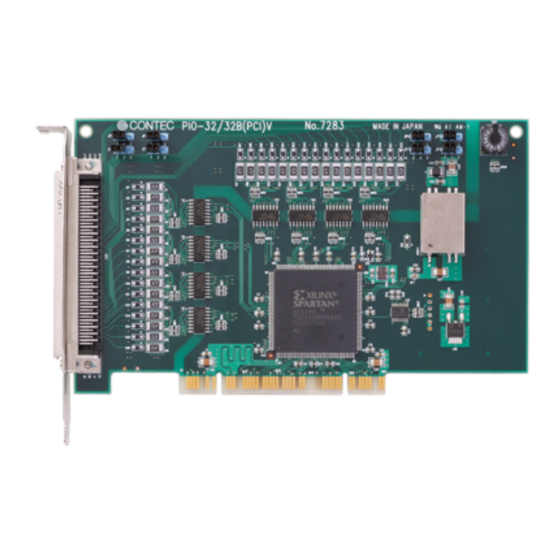
Figure 2.1. shows the names of major parts on the board. Note that the switch setting shown below is the factory default. - Power supply select jumper (JP2 - JP9) JP2 - 9 PIO-32/32B(PCI)V BOARD ID - BOARD ID Setting Switch BOARD ID - Interface connector (CN1) Figure 2.1. -
Page 23: Setting The Board Id
Setting Procedure To set the board ID, use the rotary switch on the board. Turn the SW1 knob to set the board ID as shown below. BOARD ID Factory setting: (Board ID= 0) Figure 2.2. Board ID Settings (SW1) PIO-32/32B(PCI)V... -
Page 24: Selecting Power Supply
+0 port (Input) +1 port (Input) +2 port (Input) +3 port (Input) +4 port (Output) +5 port (Output) +6 port (Output) +7 port (Output) * Factory setting Notes : These jumpers must be set in pairs. Figure 2.3. Power Supply Selecting PIO-32/32B(PCI)V... -
Page 25: Plugging The Board
Make sure that your PC or expansion unit can supply ample power to all the boards installed. Insufficiently energized boards could malfunction, overheat, or cause a failure. Power supply from the PCI bus slot at +5V is required. PIO-32/32B(PCI)V... -
Page 26: Step 3 Installing The Hardware
If you remove two or more boards that have already been installed and then remount one of them on the computer, it is unknown that which one of the sets of resources previously assigned to the two boards is assigned to the remounted board. In this case, you must check the resource settings. PIO-32/32B(PCI)V... -
Page 27: Found New Hardware Wizard Setting
(2) When the model name of hardware is displayed, select “Install the software automatically [Recommended]” and then click on the “Next” button. The device is automatically installed, and processing is completed. You have now finished installing the initial setting of Hardware. PIO-32/32B(PCI)V... -
Page 28: Step 4 Initializing The Software
- PIO-32/32B(PCI)V (2) The installed hardware appears under the CONTEC Devices node. Open the CONTEC Devices node and select the device you want to setup (the device name should appear highlighted). Click [Properties]. PIO-32/32B(PCI)V... - Page 29 - PIO-32/32B(PCI)V The initial device name that appears is a default value. You can use this default name if you wish. Make sure that you do not use the same name for more than one device.
-
Page 30: Step 5 Operation Checks
Set the board in the default factory. To connect an external device, see Chapter 3 “External Connection”. Starting the Diagnosis Program Open the “Properties” page of the device that was used for the software initialization, and press the [Diagnosis] button. PIO-32/32B(PCI)V... - Page 31 - PIO-32/32B(PCI)V To use the function execution time measurement feature, click on the [Measurement Time] button. Enter the I/O start port and the number of ports, then press the measurement button. The time for each execution of a function will be measured.
- Page 32 Before executing diagnosis report output, unplug the cable from the board. * The name of the board you have just added is displayed. - PIO-32/32B(PCI)V Click on [Show Diagnosis Report]. (2) A diagnosis report is displayed as shown below. * The name of the board you have tested is displayed.
-
Page 33: Setup Troubleshooting
Diagnosis Program, it will work with other applications. Review the program, paying attention to the following points. Check the return values of functions. Refer to the source code of sample program. Refer to the “Troubleshooting” in API-TOOL(WDM) HELP (APITOOL.chm) PIO-32/32B(PCI)V... -
Page 34: External Connection
To connect an external device to this board, plug the cable from the device into the interface connector (CN1). Interface connector (CN1) - Connector used PCR-E96LMD (mfd. by HONDA) equivalent - Applicable connectors PCR-E96FA (mfd. by HONDA) equivalent Figure 3.1. Connecting the Interface Connector PIO-32/32B(PCI)V... -
Page 35: Connector Pin Assignment
When the external power supply is selected, its negative side is connected to this pin. When the internal power supply is selected, this pin serves as the ground. These pins are common to 16 input signal pins. N.C. This pin is left unconnected. Figure 3.2. Pin Assignments of Interface Connector < PIO-32/32B(PCI)V > PIO-32/32B(PCI)V... - Page 36 Common ON 6/7 IN 0/1 Common ON 4/5 minus pin minus pin minus pin minus pin for +0/+1 for +2/+3 for +4/+5 for +6/+7 input ports input ports output ports output ports Figure 3.3. PCB96WS and CCB-96 Signal Assignments PIO-32/32B(PCI)V...
-
Page 37: Relationships Between Api-Pac(W32) Logical Ports/Bits And Connector Signal Pins
The following table lists the relationships between the connector signal pins and the logical port/bit numbers used for I/O functions when applications are written with API-PAC(W32). PIO-32/32B(PCI)V Table 3.1. Logical Ports, Logical Bits, and Connector Signal Pins <PIO-32/32B(PCI)V> I-07 I-06... -
Page 38: Connecting Input Signals
Figure 3.4. Input Circuit < PIO-32/32B(PCI)V > The input circuits of interface blocks of the PIO-32/32B(PCI)V are illustrated in Figure 3.4. The signal inputs are isolated by opto-couplers (ready to accept current sinking output signals). The board therefore requires an additional power supply isolated from the PC system to drive the photo-isolated circuits. -
Page 39: Connecting A Switch
Input minus common (CN1 : A01 pin) Switch When the switch is ON, the corresponding bit contains 1. When the switch is OFF, by contrast, the bit contains 0. Figure 3.5. An Example to use Input I00 < PIO-32/32B(PCI)V > PIO-32/32B(PCI)V... -
Page 40: Connecting Output Signals
* Output pin represent output signals. Figure 3.6. Output Circuit <PIO-32/32B(PCI)V> The output circuits of interface blocks of the PIO-32/32B(PCI)V are illustrated in Figure 3.6. The signal output section is an opto-coupler isolated, open-collector output (current sink type). Driving the output section requires an additional power supply isolated from the PC system. -
Page 41: Connection To The Led
Example of Connection to TTL Level Input External powwer supply 12 - 24VDC Input board Output plus common 2kΩ Output TTL level input Output minus common Figure 3.8. Connection Example of Output and TTL level Input Signal < PIO-32/32B(PCI)V > PIO-32/32B(PCI)V... -
Page 42: Connecting The Sink Type Output And Sink Output Support Input
12 - 24VDC Output board Input board Input plus common Output plus common Output (sink type) Input (Compatible with sink output) Output minus common Figure 3.9. Example of Connecting the Sink Type Output and Sink Output Support Input PIO-32/32B(PCI)V... - Page 43 3. External Connection PIO-32/32B(PCI)V...
-
Page 44: Function
When “0” is output to the relevant bit, in contrast, the corresponding transistor is set to “OFF”. CAUTION When the PC is turned on, all output are reset to 0 (OFF). Monitoring Output Data The <PIO-32/32B(PCI)V> can read the state of the data currently being output without affecting the output data. PIO-32/32B(PCI)V... -
Page 45: Digital Filter Function
If you set the digital filter time, the filter applies to all input pins. You cannot apply the filter only to a specific input pin. Do not set a value outside the above range to the Setting Data as doing so can cause the board to malfunction. PIO-32/32B(PCI)V... -
Page 46: Interrupt Control Function
4. Function Interrupt Control Function The PIO-32/32B(PCI)V can use all of the input signals as interrupt request signals. The board can generate an interrupt request signal to the PC when the input signal change from High to Low or from Low to High. - Page 47 4. Function PIO-32/32B(PCI)V...
-
Page 48: About Software
From the Start menu, click "CONTEC API-PAC(W32)" - "API-TOOL(WDM) HELP". When this link does not exist, From the Start menu, click "CONTEC API-PAC(W32)" - "API-DIO(WDM)" - "API-DIO(WDM) HELP". * For the API-DIO(98/PC) driver, From the Start menu, click "CONTEC API-PAC(W32)" - "API-DIO(98/PC)" - "API-DIO HELP". PIO-32/32B(PCI)V... -
Page 49: Using Sample Programs
* When the installation folder is changed, the folder of the sample program is different. Running a Sample Program (1) Click on the [Start] button on the Windows taskbar. (2) For the API-DIO(WDM), from the Start Menu, select “Programs” – “CONTEC API-PAC(W32)” – “API-DIO(WDM)” – “SAMPLE…”. (3) A sample program is invoked. -
Page 50: Uninstalling The Driver Libraries
Use [My Computer] - [Control Panel] - [Programs and Features] to uninstall the development environment. In case of API-***(WDM), select [CONTEC API-***(WDM) VerX.XX (Develop)] and then click [Uninstall]. * "***" contains the driver category name (AIO, CNT, DIO, SMC, etc.). -
Page 51: About Software For Linux
# mount /dev/cdrom /mnt/cdrom Mount the bundled disk. # cp /mnt/cdrom/linux/dio/cdioXXX.tgz ./ Copy the compressed file. # tar xvfz cdioXXX.tgz Decompress the compressed file....# cd contec/cdio # make Compile the file....# make install Install....# cd config # ./config... -
Page 52: Accessing The Help File
Sample programs for each language are contained in the contec/cdio/samples directory. For compiling them, refer to the manual for the desired language. Uninstalling the driver To uninstall the driver, use the uninstall shell script contained in the contec/cdio directory. For details, check the contents of the script. PIO-32/32B(PCI)V... - Page 53 5. About Software PIO-32/32B(PCI)V...
-
Page 54: About Hardware
6. About Hardware About Hardware This chapter provides hardware specifications and hardware-related supplementary information. Hardware specifications Table 6.1. Specifications < PIO-32/32B(PCI)V > < 1 /2 > Item Specifications Input Input format Opto-isolated input (Compatible with current sink output)(Negative logic *1) - Page 55 6. About Hardware Table 6.1. Specifications < PIO-32/32B(PCI)V> <2/2> Item Specifications Common Power consumption 5VDC 300mA(Max.) (Using the external power) 5VDC 1050mA(Max.)(Using the internal power) Operating condition 0 - 50°C, 10 - 90%RH(No condensation) Allowable distance Approx. 50m (depending on wiring environment)
-
Page 56: Block Diagram
(8 channels, Group 5) Transistors Opto- External Digital coupler Output Port2 & (8 channels, Group 6) Transistors Interrupt Control Circuit Opto- External Digital coupler Output Port3 & (8 channels, Group 7) Transistors PIO-32/32B(PCI)V Figure 6.1. Block Diagram < PIO-32/32B(PCI)V> PIO-32/32B(PCI)V... -
Page 57: Differences Between The Pio-32/32B(Pci)V And Pio-32/32B(Pci)H
6. About Hardware Differences between the PIO-32/32B(PCI)V and PIO-32/32B(PCI)H The PIO-32/32B(PCI)V is connector-pin compatible with the conventional PIO-32/32B(PCI)H but has the following differences from it: (1) Different in the number of input signals available to interrupt requests PIO-32/32B(PCI)V : All of 32 channels... - Page 59 January 2018 Edition 3-9-31, Himesato, Nishiyodogawa-ku, Osaka 555-0025, Japan https://www.contec.com/ No part of this document may be copied or reproduced in any form by any means without prior written consent of CONTEC CO., LTD. [01262018] [03242005] Management No. A-46-969 [01262018_rev2] Parts No.
Need help?
Do you have a question about the PIO-32/32B(PCI)V and is the answer not in the manual?
Questions and answers