Table of Contents

Subscribe to Our Youtube Channel
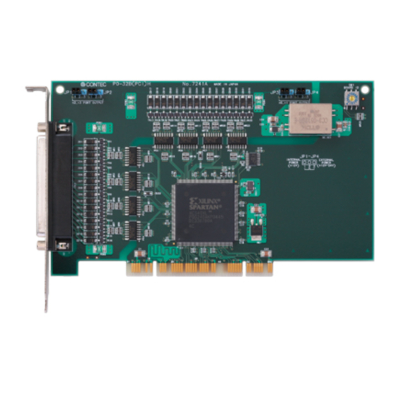
Related Manuals for Contec PIO-16/16B(PCI)H


Summary of Contents for Contec PIO-16/16B(PCI)H
- Page 1 PC-HELPER Digital I/O Board with Opto-Isolation for PCI PIO-16/16B(PCI)H Digital Input Board with Opto-Isolation for PCI PI-32B(PCI)H Digital Output Board with Opto-Isolation for PCI PO-32B(PCI)H User’s Guide CONTEC CO., LTD.
- Page 2 Check Your Package Thank you for purchasing the CONTEC product. The product consists of the items listed below. Check, with the following list, that your package is complete. If you discover damaged or missing items, contact your retailer. Product Configuration List - Board (One of the followings) …1...
- Page 3 PI-32B(PCI)H, PO-32B(PCI)H Disk Board [API-PAC(W32)] First step guide Warranty Certificate First step guide Warranty Certificate Serial Number Label PIO-16/16B(PCI)H, PI-32B(PCI)H, PO-32B(PCI)H...
-
Page 4: Copyright
No part of this document may be copied or reproduced in any form by any means without prior written consent of CONTEC CO., LTD. CONTEC CO., LTD. makes no commitment to update or keep current the information contained in this document. The information in this document is subject to change without notice. -
Page 5: Table Of Contents
Selecting the internal or external power supply ................17 Plugging the Board ..........................18 Step 3 Installing the Hardware ......................... 19 Turning on the PC ..........................19 Found New Hardware Wizard Setting ....................20 Step 4 Initializing the Software........................ 21 PIO-16/16B(PCI)H, PI-32B(PCI)H, PO-32B(PCI)H... - Page 6 Using Sample Programs ........................44 Uninstalling the Driver Libraries...................... 45 About Software for Linux......................... 46 Procedure for Installing the Driver ....................46 Accessing the Help File ........................46 Using Sample Programs ........................47 Uninstalling the Driver ........................47 PIO-16/16B(PCI)H, PI-32B(PCI)H, PO-32B(PCI)H...
- Page 7 Hardware specifications ........................... 49 Block Diagram............................53 Differences in board dimensions of PIO-16/16B(PCI)H ................56 Differences between the PIO-16/16B(PCI)H No.7238x and PIO-16/16B(PCI) ..........56 Differences between the PI-32B(PCI)H and PI-32B(PCI) ................. 57 Differences between the PO-32B(PCI)H and PO-32B(PCI) ..............57...
-
Page 8: Before Using The Product
This board is a PCI-compliant interface board for input/output of digital signals. The PC can be used to input the on/off state of a switch and to control a relay. <PIO-16/16B(PCI)H> can input and output up to 16 channels. <PI-32B(PCI)H> can input up to 32 channels. -
Page 9: Support Software
(DLL). Various sample programs such as Visual Basic and Visual C++, etc and diagnostic program *1useful for checking operation is provided. For more details on the supported OS, applicable language and new information, please visit the CONTEC’s Web site. Linux version of digital I/O driver API-DIO(LNX) -
Page 10: Accessories (Option)
: CM-32L *1 *1 A PCB37P or PCB37PS optional cable is required separately. *2 "Spring-up" type terminal is used to prevent terminal screws from falling off. * Check the CONTEC’s Web site for more information on these options. PIO-16/16B(PCI)H, PI-32B(PCI)H, PO-32B(PCI)H... -
Page 11: Customer Support
You can download updated driver software and differential files as well as sample programs available in several languages. Note! For product information Contact your retailer if you have any technical question about a CONTEC product or need its price, delivery time, or estimate information. Limited Three-Years Warranty CONTEC Interface boards are warranted by CONTEC CO., LTD. -
Page 12: Safety Precautions
WARNING indicates a potentially hazardous situation which, if not avoided, could WARNING result in death or serious injury. CAUTION indicates a potentially hazardous situation which, if not avoided, may CAUTION result in minor or moderate injury or in property damage. PIO-16/16B(PCI)H, PI-32B(PCI)H, PO-32B(PCI)H... -
Page 13: Handling Precautions
Even when using the product continuously, be sure to read the manual and understand the contents. Do not modify the product. CONTEC will bear no responsibility for any problems, etc., resulting from modifying this product. Regardless of the foregoing statements, CONTEC is not liable for any damages whatsoever (including damages for loss of business profits) arising out of the use or inability to use this CONTEC product or the information contained herein. -
Page 14: Environment
(3) Store the package at room temperature at a place free from direct sunlight, moisture, shock, vibration, magnetism, and static electricity. Disposal When disposing of the product, follow the disposal procedures stipulated under the relevant laws and municipal ordinances. PIO-16/16B(PCI)H, PI-32B(PCI)H, PO-32B(PCI)H... - Page 15 1. Before Using the Product PIO-16/16B(PCI)H, PI-32B(PCI)H, PO-32B(PCI)H...
-
Page 16: Setup
Using the Board under an OS Other than Windows For using the board under an OS other than Windows, see the following parts of this user’s guide. This chapter Step 2 Setting the Hardware Chapter 3 External Connection Chapter 6 About Hardware PIO-16/16B(PCI)H, PI-32B(PCI)H, PO-32B(PCI)H... -
Page 17: Step 1 Installing The Software
This section describes how to install the Driver libraries. Before installing the hardware in a PC, install "Driver Library API-PAC(W32)" from the bundled media or download and install the latest edition of this software from the CONTEC web site. Although some user interfaces are different depending on the OS used, the basic procedure is the same. - Page 18 If the panel does not appear, run (drive letter):\AUTORUN.exe. (3) Click on the [Install Development or Execution Environment] button. CAUTION Before installing the software in Windows 2000 or later, log in as a user with administrator privileges. PIO-16/16B(PCI)H, PI-32B(PCI)H, PO-32B(PCI)H...
-
Page 19: Select Api-Dio(Wdm)
Clicking the [API-DIO] button under the “Detail” displays detailed information about API-DIO(WDM) and API-DIO(98/PC). Run the installation (1) Complete the installation by following the instructions on the screen. (2) The Readme file appears when the installation is complete. PIO-16/16B(PCI)H, PI-32B(PCI)H, PO-32B(PCI)H... -
Page 20: Step 2 Setting The Hardware
Note that the switch setting shown below is the factory default. - Built-in power setting function - Interface connector - Board ID setting switch PIO/PI/PO-xx(PCI)H BOARD ID (CN1) (SW1) BOARD ID - Built-in power setting function Figure 2.1. Component Locations <PIO-16/16B(PCI)H> Board No.8756x PIO-16/16B(PCI)H, PI-32B(PCI)H, PO-32B(PCI)H... - Page 21 2. Setup - Supply power setting jumper (JP1 - JP4) JP1 to 4 PIO/PI/PO-xx(PCI)H BOARD ID - Board ID setting switch BOARD ID - Interface connector (CN1) Figure 2.2. Component Locations <PIO-16/16B(PCI)H> Board No.7238, No.7238A, No.7238B PIO-16/16B(PCI)H, PI-32B(PCI)H, PO-32B(PCI)H...
- Page 22 2. Setup - Supply power setting jumper (JP1 - JP4) JP1 to 4 PIO/PI/PO-xx(PCI)H BOARD ID - Board ID setting switch BOARD ID - Interface connector (CN1) Figure 2.3. Component Locations <PI-32B(PCI)H>, <PO-32B(PCI)H> PIO-16/16B(PCI)H, PI-32B(PCI)H, PO-32B(PCI)H...
-
Page 23: Setting The Board Id
To set the board ID, use the rotary switch on the board. Turn the SW1 knob to set the board ID as shown below. BOARD ID Factory setting: (Board ID = 0) Figure 2.4. Board ID Settings (SW1) PIO-16/16B(PCI)H, PI-32B(PCI)H, PO-32B(PCI)H... -
Page 24: Selecting The Internal Or External Power Supply
Note : Be sure to set these jumpers in pairs. On the PIO-16/16B(PCI)H, ports +0 and +1 serve as inputs and ports +2 and +3 serve as outputs. On the PI-32B(PCI)H, all of ports +0 - +3 serve as inputs. -
Page 25: Plugging The Board
Make sure that your PC or expansion unit can supply ample power to all the boards installed. Insufficiently energized boards could malfunction, overheat, or cause a failure. Power supply from the PCI bus slot at +5V is required. PIO-16/16B(PCI)H, PI-32B(PCI)H, PO-32B(PCI)H... -
Page 26: Step 3 Installing The Hardware
If you remove two or more boards that have already been installed and then remount one of them on the computer, it is unknown that which one of the sets of resources previously assigned to the two boards is assigned to the remounted board. In this case, you must check the resource settings. PIO-16/16B(PCI)H, PI-32B(PCI)H, PO-32B(PCI)H... -
Page 27: Found New Hardware Wizard Setting
(2) When the model name of hardware is displayed, select “Install the software automatically [Recommended]” and then click on the “Next” button. The device is automatically installed, and processing is completed. You have now finished installing the initial setting of Hardware. PIO-16/16B(PCI)H, PI-32B(PCI)H, PO-32B(PCI)H... -
Page 28: Step 4 Initializing The Software
- PI-32B(PCI)H “DI000” - PO-32B(PCI)H “DO000” (2) The installed hardware appears under the CONTEC Devices node. Open the CONTEC Devices node and select the device you want to setup (the device name should appear highlighted). Click [Properties]. PIO-16/16B(PCI)H, PI-32B(PCI)H, PO-32B(PCI)H... - Page 29 The initial device name that appears is a default value. You can use this default name if you wish. Make sure that you do not use the same name for more than one device. You have now finished installing the initial setting of Software. PIO-16/16B(PCI)H, PI-32B(PCI)H, PO-32B(PCI)H...
-
Page 30: Step 5 Operation Checks
Set the board in the default factory. To connect an external device, see Chapter 3 “External Connection”. Starting the Diagnosis Program Open the “Properties” page of the device that was used for the software initialization, and press the [Diagnosis] button. PIO-16/16B(PCI)H, PI-32B(PCI)H, PO-32B(PCI)H... - Page 31 To use the function execution time measurement feature, click on the [Measurement Time] button. Enter the I/O start port and the number of ports, then press the measurement button. The time for each execution of a function will be measured. PIO-16/16B(PCI)H, PI-32B(PCI)H, PO-32B(PCI)H...
- Page 32 CAUTION Before executing diagnosis report output, unplug the cable from the board. * The name of the board you have just added is displayed. - PIO-16/16B(PCI)H - PI-32B(PCI)H - PO-32B(PCI)H Click on [Show Diagnosis Report]. PIO-16/16B(PCI)H, PI-32B(PCI)H, PO-32B(PCI)H...
-
Page 33: Setup Troubleshooting
Diagnosis Program, it will work with other applications. Review the program, paying attention to the following points. Check the return values of functions. Refer to the source code of sample program. Refer to the “Troubleshooting” in API-TOOL(WDM) HELP (APITOOL.chm) PIO-16/16B(PCI)H, PI-32B(PCI)H, PO-32B(PCI)H... -
Page 34: External Connection
17JE-23370-02(D8C) (mfd. by DDK, Male), FDCD-37P (mfd. by HIROSE, Male), DC-37P-N (mfd. by JAE, Male), or equivalent * Please refer to chapter 1 for more information on the supported cable and accessories. Figure 3.1. Interface Connector and Applicable Cable Connector PIO-16/16B(PCI)H, PI-32B(PCI)H, PO-32B(PCI)H... -
Page 35: Connector Pin Assignment
When the external power supply is selected, its negative side is connected to this pin. When the internal power supply is selected, this pin serves as the ground. These pins are common to 16 output signal pins. N.C. This pin is left unconnected. Figure 3.2. Pin Assignments of Interface Connector <PIO-16/16B(PCI)H> PIO-16/16B(PCI)H, PI-32B(PCI)H, PO-32B(PCI)H... - Page 36 N0, N1 When the internal power supply is selected, this pin serves as the ground. These pins are common to 16 input signal pins. N.C. This pin is left unconnected. Figure 3.3. Pin Assignments of Interface Connector <PI-32B(PCI)H> PIO-16/16B(PCI)H, PI-32B(PCI)H, PO-32B(PCI)H...
- Page 37 N0, N1 When the internal power supply is selected, this pin serves as the ground. These pins are common to 16 input signal pins. N.C. This pin is left unconnected. Figure 3.4. Pin Assignments of Interface Connector <PO-32B(PCI)H> PIO-16/16B(PCI)H, PI-32B(PCI)H, PO-32B(PCI)H...
-
Page 38: Relationships Between Api-Pac(W32) Logical Ports/Bits And Connector Signal Pins
The following table lists the relationships between the connector signal pins and the logical port/bit numbers used for I/O functions when applications are written with API-PAC(W32). PIO-16/16B(PCI)H Table 3.1. Logical Ports, Logical Bits, and Connector Signal Pins <PIO-16/16B(PCI)H> I-07 I-06... - Page 39 Note: O-xx represent output signals, respectively, where [xx] indicates a logical bit. CAUTION The logical port and logical bit numbers are virtual port and bit numbers that enable programming independent of board I/O addresses or board types. For details, refer to HELP after installing API-PAC(W32). PIO-16/16B(PCI)H, PI-32B(PCI)H, PO-32B(PCI)H...
-
Page 40: Connecting Input Signals
* Input pin represent inpu t signals. Figure 3.5. Input Circuit <PIO-16/16B(PCI)H>, <PI-32B(PCI)H> The input circuits of interface blocks of the PIO-16/16B(PCI)H and PI-32B(PCI)H are illustrated in Figure 3.5. The signal inputs are isolated by opto-couplers (ready to accept current sinking output signals). -
Page 41: Connecting A Switch
Input minus common (CN1 : 1pin) Switch When the switch is ON, the corresponding bit contains 1. When the switch is OFF, by contrast, the bit contains 0. Figure 3.6. An Example to use Input I00 <PIO-16/16B(PCI)H>, <PI-32B(PCI)H> PIO-16/16B(PCI)H, PI-32B(PCI)H, PO-32B(PCI)H... -
Page 42: Output Circuit
* Output pin represent output signals. Figure 3.7. Output Circuit <PIO-16/16B(PCI)H>, <PO-32B(PCI)H> The output circuits of interface blocks of the PIO-16/16B(PCI)H and PO-32B(PCI)H are illustrated in Figure 3.7. The signal output section as an opto-coupler-isolated open-collector output (current sink type). To drive the output section, the on-board internal power supply must be used or an external power supply is required. -
Page 43: Connection To The Led
Example of Connection to TTL Level Input External power supply 12 - 24VDC Input board Output plus common 2kΩ Output TTL level input Output minus common Figure 3.9. Connection Example of Output and TTL level Input Signal <PIO-16/16B(PCI)H>, <PO-32B(PCI)H> PIO-16/16B(PCI)H, PI-32B(PCI)H, PO-32B(PCI)H... -
Page 44: Connecting The Sink Type Output And Sink Output Support Input
12 - 24VDC Output board Input board Input plus common Output plus common Output (sink type) Input (Compatible with sink output) Output minus common Figure 3.10. Example of Connecting the Sink Type Output and Sink Output Support Input PIO-16/16B(PCI)H, PI-32B(PCI)H, PO-32B(PCI)H... - Page 45 3. External Connection PIO-16/16B(PCI)H, PI-32B(PCI)H, PO-32B(PCI)H...
-
Page 46: Function
When “0” is output to the relevant bit, in contrast, the corresponding transistor is set to “OFF”. CAUTION When the PC is turned on, all output are reset to 0 (OFF). Monitoring Output Data The <PIO-16/16B(PCI)H> and <PO-32B(PCI)H> can read the state of the data currently being output without affecting the output data. PIO-16/16B(PCI)H, PI-32B(PCI)H, PO-32B(PCI)H... -
Page 47: Digital Filter Function
4. Function Digital Filter Function Using this feature, the PIO-16/16B(PCI)H and PI-32B(PCI)H can apply a digital filter to every input pin, thereby preventing wrong recognition of input signals from being affected by noise or chattering. Digital Filter Function Principle The digital filter checks the input signal level during the sampling time of the clock signal. When the signal level remains the same for the digital filter set time, the digital filter recognizes that signal as the input signal and changes the signal level of the PC. -
Page 48: Disabling/Enabling Interrupts
4. Function The PIO-16/16B(PCI)H and PI-32B(PCI)H can use all of the input signals as interrupt request signals. The board can generate an interrupt request signal to the PC when the input signal change from High to Low or from Low to High. - Page 49 4. Function PIO-16/16B(PCI)H, PI-32B(PCI)H, PO-32B(PCI)H...
-
Page 50: About Software
From the Start menu, click "CONTEC API-PAC(W32)" - "API-TOOL(WDM) HELP". When this link does not exist, From the Start menu, click "CONTEC API-PAC(W32)" - "API-DIO(WDM)" - "API-DIO(WDM) HELP". * For the API-DIO(98/PC) driver, From the Start menu, click "CONTEC API-PAC(W32)" - "API-DIO(98/PC)" - "API-DIO HELP". PIO-16/16B(PCI)H, PI-32B(PCI)H, PO-32B(PCI)H... -
Page 51: Using Sample Programs
* When the installation folder is changed, the folder of the sample program is different. Running a Sample Program (1) Click on the [Start] button on the Windows taskbar. (2) For the API-DIO(WDM), from the Start Menu, select “Programs” – “CONTEC API-PAC(W32)” – “API-DIO(WDM)” – “SAMPLE…”. (3) A sample program is invoked. -
Page 52: Uninstalling The Driver Libraries
Use [My Computer] - [Control Panel] - [Programs and Features] to uninstall the development environment. In case of API-***(WDM), select [CONTEC API-***(WDM) VerX.XX (Develop)] and then click [Uninstall]. * "***" contains the driver category name (AIO, CNT, DIO, SMC, etc.). -
Page 53: About Software For Linux
# cd config # ./config Set up the board to be used..Set as follows ..# ./contec_dio_start.sh Start the driver. # cd Accessing the Help File (1) Invoke a web browser in your X-Window environment. PIO-16/16B(PCI)H, PI-32B(PCI)H, PO-32B(PCI)H... -
Page 54: Using Sample Programs
Sample programs for each language are contained in the contec/cdio/samples directory. For compiling them, refer to the manual for the desired language. Uninstalling the Driver To uninstall the driver, use the uninstall shell script contained in the contec/cdio directory. For details, check the contents of the script. PIO-16/16B(PCI)H, PI-32B(PCI)H, PO-32B(PCI)H... - Page 55 5. About Software PIO-16/16B(PCI)H, PI-32B(PCI)H, PO-32B(PCI)H...
-
Page 56: About Hardware
6. About Hardware 6. About Hardware This chapter provides hardware specifications and hardware-related supplementary information. Hardware specifications PIO-16/16B(PCI)H Table 6.1. Specifications < PIO-16/16B(PCI)H > Item Specification Input Input format Opto-isolated input (Compatible with current sink output) (Negative logic *1) Number of input signal channels... - Page 57 Board No.7238, No.7238A, and No.7238B 176.41(L) [mm] The standard outside dimension (L) is the distance from the end of the board to the outer surface of the slot cover. PIO-16/16B(PCI)H, PI-32B(PCI)H, PO-32B(PCI)H...
- Page 58 This board requires +5V power supply from expansion slots (it does not operate in the environment of only +3.3V power supply). Board Dimensions 176.41(L) [mm] The standard outside dimension (L) is the distance from the end of the board to the outer surface of the slot cover. PIO-16/16B(PCI)H, PI-32B(PCI)H, PO-32B(PCI)H...
- Page 59 This board requires +5V power supply from expansion slots (it does not operate in the environment of only +3.3V power supply). Board Dimensions 176.41(L) [mm] The standard outside dimension (L) is the distance from the end of the board to the outer surface of the slot cover. PIO-16/16B(PCI)H, PI-32B(PCI)H, PO-32B(PCI)H...
-
Page 60: Block Diagram
(8 channels, Group 1) Control Circuits Opto- Output Port 0 coupler & (8 channels, Group 2) Transistors Output Port 1 Opto- coupler (8 channels, Group 3) & Transistors Interrupt Control Circuit PIO-16/16B(PCI)H Figure 6.1. Block Diagram < PIO-16/16B(PCI)H> PIO-16/16B(PCI)H, PI-32B(PCI)H, PO-32B(PCI)H... - Page 61 Input Port 1 Opto- coupler (8 channels, Group 1) Control Circuits Input Port 2 Opto- coupler (8 channels, Group 2) Input Port 3 Opto- coupler (8 channels, Group 3) Interrupt Control Circuit PI-32B(PCI)H Figure 6.2. Block Diagram < PI-32B(PCI)H> PIO-16/16B(PCI)H, PI-32B(PCI)H, PO-32B(PCI)H...
- Page 62 & (8 channels, Group 1) Transistors Control Circuits Opto- Output Port 2 coupler & (8 channels, Group 2) Transistors Opto- Output Port 3 coupler & (8 channels, Group 3) Transistors PO-32B(PCI)H Figure 6.3. Block Diagram < PO-32B(PCI)H> PIO-16/16B(PCI)H, PI-32B(PCI)H, PO-32B(PCI)H...
-
Page 63: Differences In Board Dimensions Of Pio-16/16B(Pci)H
6. About Hardware Differences in board dimensions of PIO-16/16B(PCI)H The board dimensions of PIO-16/16B(PCI)H differ depending on board number. There is no change in electrical specifications other than board dimensions. (1) Different in board dimensions No.7238x : 176.41(L) x 105.68(H) mm No.8756x... -
Page 64: Differences Between The Pi-32B(Pci)H And Pi-32B(Pci)
The PO-32B(PCI)H is connector-pin compatible with the conventional PO-32B(PCI) but has the following differences from it: (1) Protective elements provided for outputs PO-32B(PCI)H : Surge protector: Zener diode PO-32B(PCI) : Nothing (2) Different in board dimensions PO-32B(PCI)H : 176.41(L) x 105.68(H) mm PO-32B(PCI) : 176.41(L) x 106.68(H) mm PIO-16/16B(PCI)H, PI-32B(PCI)H, PO-32B(PCI)H... - Page 65 November 2018 Edition 3-9-31, Himesato, Nishiyodogawa-ku, Osaka 555-0025, Japan https://www.contec.com/ No part of this document may be copied or reproduced in any form by any means without prior written consent of CONTEC CO., LTD. [11152018] [11142003] Management No. A-46-722 [11152018_rev6] Parts No.
Need help?
Do you have a question about the PIO-16/16B(PCI)H and is the answer not in the manual?
Questions and answers