Table of Contents
Advertisement
Quick Links
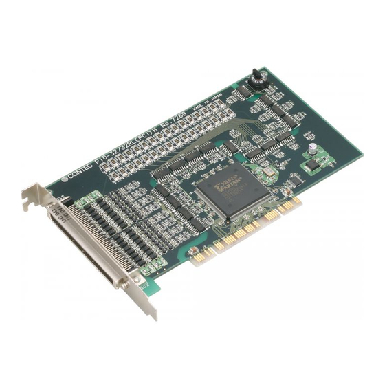
Current Source Digital I/O Board
with Opto-Isolation
PIO-32/32RL(PCI)H
* Specifications, color and design of the products are subject to
change without notice.
Features
A different external power supply can be used for each
common pin as it is shared by 16 channels.
The PCI bus (personal computer) and the I/O interface are
isolated from each other by an Optocoupler, offering good
noise immunity.
You can use 32 signal channels of the input signals as interrupt
inputs.
You can also select the interrupt trigger edge of the input
signal.
The board has a digital filter feature to prevent noise or chatter
from causing erroneous inputs.
Up to 35VDC, 100mA per signal, max. output.
Zener diode connected to output transistors for protection from
surge voltage.
Overcurrent protective device provided for
every eight channels of output transistors.
Packing List
Board [PIO-32/32RL(PCI)H] ...1
First step guide ... 1
CD-ROM *1 [API-PAC(W32)] ...1
*1
The CD-ROM contains the driver software and User's Guide.
PIO-32/32RL(PCI)H
This board is a PCI bus-compliant interface board for
input/output of digital signals.
The board is a current source typed and isolated digital
input/output board and can input and output digital signals at
12 - 24VDC.
This board can input and output up to 32 channels.
This product uses Optocoupler isolated input (ready to accept
current sinking output signals) for input and Optocoupler
isolated current sinking output for output.
Using the bundled driver library [API-PAC(W32)], you can
create Windows application software for this board in your
favorite
programming
language
functions, such as Visual Basic or Visual C++.
Specification
Item
Input
Input format
Optocoupler isolated input (corresponding to the current source
output)(Negative logic *1)
Number of input signal
32 channels (all available for interrupts) (One common power
channels
supply per 16 channels)
Input resistance
4.7kΩ
Input ON current
2.0mA or more
Input OFF current
0.16mA or less
Interrupt
32 interrupt input signals are arranged into a single output of
interrupt signal INTA.
An interrupt is generated at the falling edge (HIGH-to-LOW
transition) or rising edge (LOW-to-HIGH transition).
Response time
200μsec within
Output
Output format
Optocoupler isolated (Compatible with current source
output)(Negative logic *1)
Number of output signal
32 channels (One common power supply per 16 channels)
channels
Output
Output voltage 35VDC (Max.)
rating Output current
100mA (par channel) (Max. )
Residual voltage with
0.5V or less (Output current≤50mA), 1.0V or less (Output
output on
current≤100mA)
Surge protector
Zener diode RD47FM(NEC) or the equivalence for it
Response time
200μsec within
Common
I/O address
8 bits x 32 ports
Interruption level
1 level use
Max. board count for
16 boards including the master board
connection
Dielectric strength
500Vrms
External circuit power
12 - 24VDC(±10%)
supply
Power consumption
5VDC 200mA(Max.)
Operating condition
0 - 50°C, 10 - 90%RH(No condensation)
Allowable distance of
Approx. 50m (depending on wiring environment)
signal extension
PCI bus specification
32bit, 33MHz, Universal key shapes supported *2
Dimension (mm)
176.41(L) x 105.68(H)
Weight
215g
*1
Data "0" and "1" correspond to the High and Low levels, respectively.
*2
This board requires power supply at +5V from an expansion slot (it does not work on a
machine with a +3.3V power supply alone).
Board Dimensions
176.41(L)
The standard outside dimension (L) is
the distance from the end of the board to
the outer surface of the slot cover.
Ver.1.11
supporting
Win32
API
Specification
[mm]
1
Advertisement
Table of Contents

Subscribe to Our Youtube Channel
Related Manuals for Contec PIO-32/32RL(PCI)H


Summary of Contents for Contec PIO-32/32RL(PCI)H
- Page 1 Packing List Operating condition 0 - 50°C, 10 - 90%RH(No condensation) Allowable distance of Approx. 50m (depending on wiring environment) Board [PIO-32/32RL(PCI)H] …1 signal extension First step guide … 1 PCI bus specification 32bit, 33MHz, Universal key shapes supported *2 Dimension (mm) 176.41(L) x 105.68(H)
- Page 2 Option cable PCB96P or PCB96PS, and the cable for 37-pin D-SUB are required For details, read Help on the bundled CD-ROM or visit the separately. CONTEC’s Web site. Check the CONTEC’s Web site for more information on these options. < Operating environment > RedHatLinux, TurboLinux, etc.. Block Diagram (For details on supported distributions, refer to Help available after installation.)
- Page 3 OP 4/5 - OP 6/7 Connect the positive side of the external power supply. These pins are common to 16 output signal pins. IP 0/1 - IP 2/3 Connect the positive side of the external power supply. These pins are common to 16 input signal pins. N.C. This pin is left unconnected. PIO-32/32RL(PCI)H...
- Page 4 Output plus common (CN1 : B19pin) External power supply 5kΩ 12 - 24VDC O-40 (CN1 : B03pin) When outputting 1 to the corresponding bit, LED is ON. When outputting 0 to the corresponding bit, by contrast, LED is off. PIO-32/32RL(PCI)H...
Need help?
Do you have a question about the PIO-32/32RL(PCI)H and is the answer not in the manual?
Questions and answers