Table of Contents
Advertisement
Quick Links
Ver.1.30
Opto-Isolated Digital I/O Board
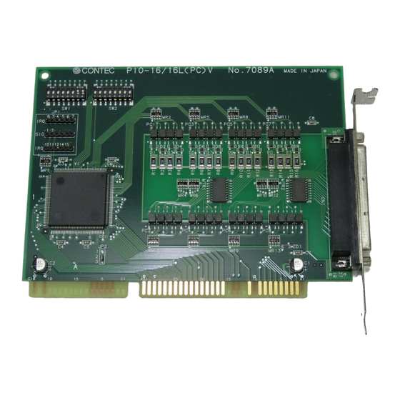
PIO-16/16L(PC)V
The PIO-16/16L(PC)V is a 16-channel digital input and
output interface board for the IBM PC/AT and compatible
computers. It can also be installed into a CONTEC I/O
expansion unit. Plugged in an ISA bus expansion slot on the
motherboard of a personal computer, can input and output
up to 16 channels.
Features
Opto-Isolated input/outputs for improved noise resistance
Up to 16 (8 signals x 2 groups) input signals
Up to 16 (8 signals x 2 groups) output signals
Two input signals can also generate interrupt requests.
Output ability: up to 35VDC, 100mA per signal, max.
Function
Input
When installed in a personal computer (PC), these boards
accept up to 16/32 digital signals (in two groups of eight) and
input them to the PC. The PC access the board for input
through four arbitrarily configurable input ports. When the
IN instruction is executed to read data through any of these
input ports, the corresponding buffer gate opens to receive
the group of digital signals from the external device. The
signals sent to the PC at this time have negative logic. The
user can assign two of the 16/32 input signals as interrupts
for the PC. These two signals can then be used as interrupt
request signals.
Output
When installed on a personal computer (PC), these boards
write up to 16/32 digital signals (in two groups of eight) to an
external device. The PC accesses the board for output
through four arbitrarily configurable output ports. When the
OUT instruction is executed to write data to any of these
output ports, the corresponding latch circuit holds the data.
The digital signals are then electrically insulated by the
photocoupler. They are output as a group to an external
device via the transistor. The signals output to the external
device at this time have negative logic. The data in the latch
circuit remains intact until the OUT instruction is executed
again.
Specification
Item
Input
Type
Opto-Isolated Input (for current sinking output) (Negative logic)
Resister
3kΩ
Current required to turn ON 3.4mA (Min.)
Current required to turn OFF 0.16mA (Max.)
Number of Channels
16 channels (2 of these 16 can be used as interrupt signal)
(16 channels with the common)
Response time
1ms (Max.)
Output
Type
Opto-Isolated Open Collector Output (current sinking type) (Negative logic)
Rating
Voltage
35VDC (Max.)
Current
100mA Max. per channel
Number of Channels
16 channels (16 channels with the common)
Response time
1ms (Max.)
Common
I/O address
Any 2-byte boundary
Interrupt
Two of IRQ 3-7,9-12,14 or 15Interrupt generated at falling edge
External power supply
12 to 24VDC (± 15%) 4mA/12V~8mA/24V per input channel
Power consumption
5VDC
50mA (Max.)
Operating condition
0 to 50° C, 20% to 90% (not condensing)
Connecting distance
50m (Typ.) (depending on wiring environment)
Dimension (mm)
163.0(L) x 122.0 (H)
Weight
120g
163.0
PIO-16/16L(PC)V
Specification
[mm]
1
Advertisement
Table of Contents

Related Manuals for Contec PIO-16/16L(PC)V


Summary of Contents for Contec PIO-16/16L(PC)V
- Page 1 The PIO-16/16L(PC)V is a 16-channel digital input and output interface board for the IBM PC/AT and compatible computers. It can also be installed into a CONTEC I/O expansion unit. Plugged in an ISA bus expansion slot on the motherboard of a personal computer, can input and output up to 16 channels.
-
Page 2: Accessories (Option)
Flat cable with a 37-pin D-SUB connector at one end: PCA37P-*(1.5m, 3m, 5m) Shielded cable with a 37-pin D-SUB connector at one end: PCA37PS-*(0.5m, 1.5m, 3m, 5m) Product Configuration List Product Configuration List - Board[PIO-16/16L(PC)V] ... 1 - This User's Manual ... 1... -
Page 3: External Connection
PIO-16/16L(PC)V Ver.1.30 External Connection Connecting the Interface Connector To connect an external device to this board, plug the cable from the device into the interface connector (CN1) shown below. C o n n e c t o r u s e d 3 7 - p i n D - S U B c o n n e c t o r ( F e m a l e ) D C L C - J 3 7 S A F - 2 0 L 9 ( m f d . -
Page 4: I/O Address Setting
PIO-16/16L(PC)V Ver.1.30 I/O Address Setting Use the on-board DIP switches (SW1 and SW2) to set the I/O base address of your board. Individual bits in SW1 and SW2 correspond to the 15 high-order bits (A15 to A1) in the I/O base address. Always set A0 to "0" (OFF) for the Board. -
Page 5: Input Port
PIO-16/16L(PC)V Ver.1.30 I/O Port Bit Assignment Input Port Output Port If input command is executed with external equipments (relay By outputting internal logic [1] (output command being point of contact, semiconductor switch, etc.) when having executed), the transistor of the last stage will be in ON state. -
Page 6: Connection Example
PIO-16/16L(PC)V Ver.1.30 Example Flow Chat Program that makes LED connected to O00 output terminal as an example of use of this board. According to ON/OFF of the external switch connected to I00 input terminal turn on switch Start off is shown below. Description language is Microsoft C. In the...
Need help?
Do you have a question about the PIO-16/16L(PC)V and is the answer not in the manual?
Questions and answers