
Related Manuals for Contec PIO-16


Summary of Contents for Contec PIO-16
- Page 1 PC-HELPER Digital I/O Board with High Voltage Isolation for PCI PIO-16/16RY(PCI) User’s Guide CONTEC CO.,LTD.
-
Page 2: Check Your Package
Check Your Package Thank you for purchasing the CONTEC product. The product consists of the items listed below. Check, with the following list, that your package is complete. If you discover damaged or missing items, contact your retailer. Product Configuration List - Board [PIO-16/16RY(PCI)]…... -
Page 3: Copyright
No part of this document may be copied or reproduced in any form by any means without prior written consent of CONTEC CO., LTD. CONTEC CO., LTD. makes no commitment to update or keep current the information contained in this document. The information in this document is subject to change without notice. -
Page 4: Table Of Contents
Step 2 Setting the Hardware......................14 Parts of the Board and Factory Defaults ................... 14 Setting the Board ID ........................15 Selecting the Input Voltage Range.................... 15 Plugging the Board ........................16 Step 3 Installing the Hardware ......................17 PIO-16/16RY(PCI) - Page 5 Digital Filter Function Principle....................34 Set Digital Filter Time....................... 34 Interrupt Control Function........................ 35 Disabling/Enabling Interrupts ....................35 Selecting the Interrupt Edge ...................... 35 Clearing the Interrupt Status and Interrupt Signal ..............35 ABOUT SOFTWARE CD-ROM Directory Structure ......................37 PIO-16/16RY(PCI)
- Page 6 Uninstalling the Driver Libraries ....................41 About Software for Linux ........................ 42 Driver Software Install Procedure..................... 42 Accessing the Help File......................43 Using Sample Programs ......................43 Uninstalling the driver....................... 43 ABOUT HARDWARE Hardware specification ........................45 Block Diagram..........................46 PIO-16/16RY(PCI)
- Page 7 PIO-16/16RY(PCI)
-
Page 8: Before Using The Product
- The board can output digital signals of up to 120 VAC/VDC through 16 channels. - A load of up to 100 mA can be driven per channel. - The PCI bus (personal computer) and the I/O interface are isolated from each other by an opto-coupler or semiconductor relay, offering good noise immunity. PIO-16/16RY(PCI) -
Page 9: Support Software
Visual Basic, Visual C++, Visual C#, Delphi, C++ Builder You can download the updated version from the CONTEC’s Web site (http://www.contec.com/apipac/). For more details on the supported OS, applicable language and new information, please visit the CONTEC’s Web site. Linux version of digital I/O driver API-DIO(LNX) -
Page 10: Cable & Connector (Option)
Signal Monitor for Digital I/O : CM-32L *1 *1 PCB37P or PCB37PS optional cable is required separately. *2 “Spring-up” type terminal is used to prevent terminal screws from falling off. * Check the CONTEC’s Web site for more information on these options. PIO-16/16RY(PCI) -
Page 11: Customer Support
You can download updated driver software and differential files as well as sample programs available in several languages. Note! For product information Contact your retailer if you have any technical question about a CONTEC product or need its price, delivery time, or estimate information. Limited Three-Years Warranty CONTEC Interface boards are warranted by CONTEC CO., LTD. -
Page 12: Safety Precautions
WARNING indicates a potentially hazardous situation which, if not avoided, could WARNING result in death or serious injury. CAUTION indicates a potentially hazardous situation which, if not avoided, may CAUTION result in minor or moderate injury or in property damage. PIO-16/16RY(PCI) -
Page 13: Handling Precautions
Even when using the product continuously, be sure to read the manual and understand the contents. Do not modify the product. CONTEC will bear no responsibility for any problems, etc., resulting from modifying this product. Regardless of the foregoing statements, CONTEC is not liable for any damages whatsoever (including damages for loss of business profits) arising out of the use or inability to use this CONTEC product or the information contained herein. -
Page 14: Environment
(3) Store the package at room temperature at a place free from direct sunlight, moisture, shock, vibration, magnetism, and static electricity. Disposal When disposing of the product, follow the disposal procedures stipulated under the relevant laws and municipal ordinances. PIO-16/16RY(PCI) - Page 15 1. Before Using the Product PIO-16/16RY(PCI)
-
Page 16: Setup
For setting up software other than API-PAC(W32), refer to the manual for that software. See also the following parts of this manual as required. This chapter Step 2 Setting the Hardware This chapter Step 3 Installing the Hardware Chapter 3 External Connection Chapter 6 About Hardware PIO-16/16RY(PCI) -
Page 17: Using The Board Under An Os Other Than Windows
Chapter 6 About Hardware For using the board under an OS such as MS-DOS other than Windows, see the following parts of this manual. This chapter Step 2 Setting the Hardware Chapter 3 External Connection Chapter 6 About Hardware PIO-16/16RY(PCI) -
Page 18: Step 1 Installing The Software
(2) The API-PAC(W32) Installer window appears automatically. If the panel does not appear, run (CD-ROM drive letter):\AUTORUN.exe. (3) Click on the [Install the drivers] button. CAUTION Before installing the software in Windows XP, 2000, or NT, log in as a user with administrator privileges. PIO-16/16RY(PCI) -
Page 19: Selecting The Digital I/O Driver
2. Setup Selecting the Digital I/O Driver (1) The following dialog box appears to select “Driver Type” and “Install Type”. (2) Select “Digital I/O API-DIO(98/PC)W95”. (3) Select “Driver, Help, etc… (Full install)”. (4) Click on the [Install] button. PIO-16/16RY(PCI) -
Page 20: Executing The Installation
2) Click on the [Finish] button. Go to Step 2 to set and plug the hardware. *When the hardware has already been installed: Check “Perform a hardware setup now”, then go to Step 4 “Initializing the Software”. You have now finished installing the software. PIO-16/16RY(PCI) -
Page 21: Step 2 Setting The Hardware
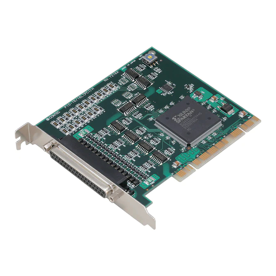
The board can be set up even with the factory defaults untouched. You can change board settings later. Parts of the Board and Factory Defaults Figure 2.1. shows the names of major parts on the board. Note that the switch setting shown below is the factory default. PIO-16/16RY(PCI) BOARD ID Board ID setting switch (SW1) -
Page 22: Setting The Board Id
Figure 2.3. Selecting the Input Voltage Range (JP1 - JP16) Jumpers correspond to input signals as follows: Input Input Input Input signal signal signal signal I-17 I-13 I-07 I-03 JP13 I-16 I-12 I-06 JP10 I-02 JP14 I-15 I-11 I-05 JP11 I-01 JP15 I-14 I-10 I-04 JP12 I-00 JP16 PIO-16/16RY(PCI) -
Page 23: Plugging The Board
Make sure that your PC or expansion unit can supply ample power to all the boards installed. Insufficiently energized boards could malfunction, overheat, or cause a failure. Power supply from the PCI bus slot at +5V is required. PIO-16/16RY(PCI) -
Page 24: Step 3 Installing The Hardware
(1) The “Found New Hardware Wizard” will be started. Select “Install from a list or specific location[Advanced]”, then click on the [Next] button. If you are using Windows NT 4.0, the “Found New Hardware Wizard” is not started. Go to Step 4 “Initializing the Software”. PIO-16/16RY(PCI) - Page 25 (2) Specify that folder on the CD-ROM which contains the setup information (INF) file to register the board. * The name of the board you have just added is displayed. - PIO-16/16RY(PCI) Source folder The setup information (INF) file is contained in the following folder on the bundled CD-ROM. Windows XP, 2000 \INF\Win2000\Dio\PCI...
- Page 26 Windows Logo testing, and it can be ignored without developing any problem with the operation of the board. In this case, click on the [Continue Anyway] button. * The name of the board you have just added is displayed. - PIO-16/16RY(PCI) You have now finished installing the software. PIO-16/16RY(PCI)
-
Page 27: Step4 Initializing The Software
The driver library requires the initial setting to recognize the execution environment. It is called the initialization of the Driver library. Invoking API-TOOL Configuration (1) Open the Start Menu, then select “Programs” – “CONTEC API-PAC(W32)” – “API-TOOL Configuration”. (2) API-TOOL Configuration detects boards automatically. -
Page 28: Step 5 Checking Operations With The Diagnosis Program
GROUP 3 GROUP 2 6 5 4 3 2 1 0 7 6 5 4 POWER Optional cable PCB37PS-xx External power supply 12 - 24 VDC To connect a device other than the Check Mate, see Chapter 3 “External Connection”. PIO-16/16RY(PCI) -
Page 29: Using The Diagnosis Program
Starting the Diagnosis Program Select the board in the API-TOOL Configuration windows, then run the Diagnosis Program. * The name of the board you have just added is displayed. * The name of the board you are testing is displayed. - PIO-16/16RY(PCI) PIO-16/16RY(PCI) - Page 30 * The name of the board you have just added is displayed. - PIO-16/16RY(PCI) To use the wait time control feature, click on the [Wait Configuration] button. Use the feature when the wait time based on the DioWait or DioWaitEx function is not normal.
- Page 31 Before executing diagnosis report output, unplug the cable from the board. * The name of the board you have just added is displayed. -PIO-16/16RY(PCI) Click on [Show Diagnosis Report]. (2) A diagnosis report is displayed as shown below. * The name of the board you have tested is displayed.
-
Page 32: Setup Troubleshooting
Turn off the power to your PC, then unplug the board. Restart the OS and delete the board settings of API-TOOL Configuration. Turn off the PC again, plug the board, and restart the OS. Let the OS detect the board and use API-TOOL Configuration to register board settings. If your problem cannot be resolved Contact your retailer. PIO-16/16RY(PCI) - Page 33 2. Setup PIO-16/16RY(PCI)
-
Page 34: External Connection
Common pin for input signals. These pins are common to 16 input signal pins. OCOM 2/3 Connect the positive side of the external power supply. These pins are common to 16 output signal pins. N.C. This pin is left unconnected. Figure 3.2. Pin Assignments of Interface Connector PIO-16/16RY(PCI) -
Page 35: Relationships Between Api-Pac(W32) Logical Ports/Bits And Connector Signal Pins
Note : I-xx represents a CAN input signal; O-xx represents a CNB output signal. [xx] represents a logical bit. CAUTION The logical port and logical bit numbers are virtual port and bit numbers that enable programming independent of board I/O addresses or board types. For details, refer to API-DIO HELP available after installing API-PAC(W32). PIO-16/16RY(PCI) -
Page 36: Connecting Input Signals
I-00 (CN1 : 2pin) 12 - 24 VDC Switch When the switch is ON, the corresponding bit contains 1. When the switch is OFF, by contrast, the bit contains 0. Figure 3.4. An Example to use Input I-00 PIO-16/16RY(PCI) -
Page 37: Examples Of Connecting The Board To An External Device
24 - 48VDC output Figure 3.5. Connecting the input to the sink type output Sourece type output External Board power supply Input 12 - 24VDC 24 - 48VDC Input common Figure 3.6. Connecting the input to the source type output PIO-16/16RY(PCI) -
Page 38: Connecting Output Signals
Output common (CN1 : 20pin) 12 - 24 VDC When "1" is output to a relevant bit, the corresponding LED comes on. When "0" is output to the bit, in contrast, the LED goes out. Figure 3.8. An Example to use Output O-20 PIO-16/16RY(PCI) -
Page 39: Examples Of Connecting The Board To An External Device
External power supply Output Output common Figure 3.9. Connecting the Output to the Sink Output Acceptable Input Board Output common External power supply Output Sourece output acceptable input Figure 3.10. Connecting the Output to the Source Output Acceptable Input PIO-16/16RY(PCI) -
Page 40: Function
When “0” is output to the relevant bit, in contrast, the corresponding transistor is set to “OFF”. CAUTION When the PC is turned on, all output are reset to 0 (OFF). Monitoring Output Data The board can read the state of the data currently being output without affecting the output data. PIO-16/16RY(PCI) -
Page 41: Digital Filter
4 (04h) 11 (0Bh) 18 (12h) 32.768msec 5 (05h) 4 μ sec 12 (0Ch) 512 μ sec 19 (13h) 65.536msec 6 (06h) 8 μ sec 13 (0Dh) 1.024msec 20 (14h) 131.072msec Figure 4.2. Digital Filter Time and Setting Data PIO-16/16RY(PCI) -
Page 42: Interrupt Control Function
All of the interrupt status bits are set to 0 when the power is turned on. If an interrupt mask bit has been set to disable interrupts, the interrupt status bit is not set even when the input signal changes its level. PIO-16/16RY(PCI) - Page 43 4. Function PIO-16/16RY(PCI)
-
Page 44: About Software
|––WDM |––Win2000 |––Win95 |––linux Linux driver file |––cnt |––dio |––…… | ––Readme Readme file for each driver | ––Release Driver file on each API-TOOL |––API_NT (For creation of a user-specific install program) |––API_W95 | ––UsersGuide Hardware User's Guide(PDF files) PIO-16/16RY(PCI) -
Page 45: About Software For Windows
Reference”, “Sample Programs”, and “FAQs”. Use them for program development and troubleshooting. Accessing the Help File (1) Click on the [Start] button on the Windows taskbar. (2) From the Start Menu, select “Programs” – “CONTEC API-PAC(W32)” – “DIO” – “API-DIO HELP” to display help information. PIO-16/16RY(PCI) -
Page 46: Using Sample Programs
The sample programs are stored in \Program Files\CONTEC\API-PAC(W32)\Dio\Samples. Running a Sample Program (1) Click on the [Start] button on the Windows taskbar. (2) From the Start Menu, select “Programs” – “CONTEC API-PAC(W32)” – “DIO” – “SAMPLE…”. (3) A sample program is invoked. PIO-16/16RY(PCI) - Page 47 Executes digital input (simple functions) at specified bits through a specified port. -Sample program 11 Services interrupts of a specified board (using an extended function). -Sample program (Console) : Inputs/outputs digital data through a specified port. [Sample program 1] [Sample program 2] [Sample program 5] [Sample program 9] PIO-16/16RY(PCI)
-
Page 48: Uninstalling The Driver Libraries
(1) Click on the [Start] button on the Windows taskbar. From the Start Menu, select “Control Panel”. (2) Double-click on “Add or Remove Programs” in the Control Panel. (3) Select “CONTEC API-DIO(98/PC)xx” from the application list displayed, then click on the [Change/Remove] button. Follow the on-screen instructions to uninstall the function libraries. -
Page 49: About Software For Linux
# mount /dev/cdrom /mnt/cdrom Mount the CD-ROM. # cp /mnt/cdrom/linux/dio/cdioXXX.tgz ./ Copy the compressed file. # tar xvfz cdioXXX.tgz Decompress the compressed file....# cd contec/cdio # make Compile the file....# make install Install....# cd config # ./config... -
Page 50: Accessing The Help File
Sample programs for each language are contained in the contec/cdio/samples directory. For compiling them, refer to the manual for the desired language. Uninstalling the driver To uninstall the driver, use the uninstall shell script contained in the contec/cdio directory. For details, check the contents of the script. PIO-16/16RY(PCI) - Page 51 5. About Software PIO-16/16RY(PCI)
-
Page 52: About Hardware
*1 This board requires power supply at +5V from an expansion slot (it does not work on a machine with a +3.3V power supply alone). *2 If the board No is 7228, “Device used” is “PS7221-2A (NEC)” and “ON resistance” is 8.0 Ω or less. PIO-16/16RY(PCI) -
Page 53: Block Diagram
(8 points, Group 0) Input Port 1 Opto-coupler (8 points, Group 1) Control Circuits Semiconductor Output Port 0 relay (8 points, Group 2) Output Port 1 Semiconductor relay (8 points, Group 3) Interrupt Control Circuit PIO-16/16RY(PCI) Figure 6.1. Block Diagram PIO-16/16RY(PCI) - Page 54 3-9-31, Himesato, Nishiyodogawa-ku, Osaka 555-0025, Japan Japanese http://www.contec.co.jp/ English http://www.contec.com/ Chinese http://www.contec.com.cn/ No part of this document may be copied or reproduced in any form by any means without prior written consent of CONTEC CO., LTD. [05222013] [05092003] Management No. A-46-742 [05222013_rev4] Parts No. LYCB562...
Need help?
Do you have a question about the PIO-16 and is the answer not in the manual?
Questions and answers