Table of Contents
Advertisement
Quick Links
Advertisement
Table of Contents

Related Manuals for Contec PIO-16H


Summary of Contents for Contec PIO-16H
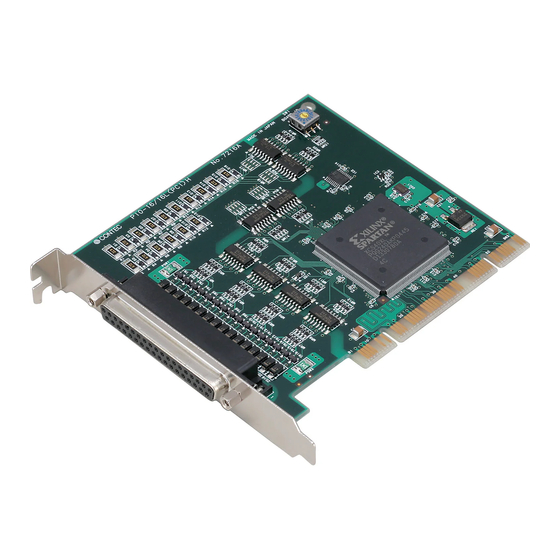
- Page 1 PC-HELPER Digital I/O Board for PCI PIO-16/16T(PCI)H User’s Guide CONTEC CO.,LTD.
- Page 2 Check Your Package Thank you for purchasing the CONTEC product. The product consists of the items listed below. Check, with the following list, that your package is complete. If you discover damaged or missing items, contact your retailer. Product Configuration List - Board [PIO-16/16T(PCI)H]…1...
-
Page 3: Copyright
No part of this document may be copied or reproduced in any form by any means without prior written consent of CONTEC CO., LTD. CONTEC CO., LTD. makes no commitment to update or keep current the information contained in this document. The information in this document is subject to change without notice. -
Page 4: Table Of Contents
Table of Contents Check Your Package..........................i Copyright ............................ii Trademarks ............................ii Table of Contents..........................iii BEFORE USING THE PRODUCT About the Board..........................1 Features ............................1 Support Software ......................... 2 Cable & Connector (Option) ...................... 3 Accessories (Option) ........................3 Customer Support .......................... - Page 5 Turning on the PC........................19 When Using API-DIO(WDM) ...................... 19 When Using API-DIO(98/PC) ...................... 22 Step 4 Initializing the Software ......................25 When Using API-DIO(WDM) ....................25 When Using API-DIO(98/PC) ....................27 Updating the Settings......................... 27 Step 5 Checking Operations with the Diagnosis Program ............... 28 What is the Diagnosis Program?....................
- Page 6 CD-ROM Directory Structure ......................45 About Software for Windows......................46 Accessing the Help File ......................46 Using Sample Programs ......................46 Uninstalling the Driver Libraries ....................48 About Software for Linux......................... 49 Driver Software Install Procedure ..................... 49 Accessing the Help File ......................50 Using Sample Programs ......................
- Page 7 PIO-16/16T(PCI)H...
-
Page 8: Before Using The Product
1. Before Using the Product 1. Before Using the Product This chapter provides information you should know before using the product. About the Board This product is a PCI bus-compliant interface board used to provide a digital signal I/O function on a PC. This product features 16 unisolated TTL level inputs and 16 unisolated open-collector outputs. -
Page 9: Support Software
Visual Basic, Visual C++, Visual C#, Delphi, C++ Builder You can download the updated version from the CONTEC’s Web site (http://www.contec.com/apipac/). For more details on the supported OS, applicable language and new information, please visit the CONTEC’s Web site. Linux version of digital I/O driver API-DIO(LNX) -
Page 10: Cable & Connector (Option)
Signal Monitor for Digital I/O (32Bits) CM-32(PC)E *1 *1 A PCB37P or PCB37PS optional cable is required separately. *2 “Spring-up” type terminal is used to prevent terminal screws from falling off. * Check the CONTEC’s Web site for more information on these options. PIO-16/16T(PCI)H... -
Page 11: Customer Support
You can download updated driver software and differential files as well as sample programs available in several languages. Note! For product information Contact your retailer if you have any technical question about a CONTEC product or need its price, delivery time, or estimate information. Limited Three-Years Warranty CONTEC Interface boards are warranted by CONTEC CO., LTD. -
Page 12: Safety Precautions
1. Before Using the Product Safety Precautions Understand the following definitions and precautions to use the product safely. Safety Information This document provides safety information using the following symbols to prevent accidents resulting in injury or death and the destruction of equipment and resources. Understand the meanings of these labels to operate the equipment safely. -
Page 13: Handling Precautions
Even when using the product continuously, be sure to read the manual and understand the contents. Do not modify the product. CONTEC will bear no responsibility for any problems, etc., resulting from modifying this product. Regardless of the foregoing statements, CONTEC is not liable for any damages whatsoever (including damages for loss of business profits) arising out of the use or inability to use this CONTEC product or the information contained herein. -
Page 14: Environment
1. Before Using the Product Environment Use this product in the following environment. If used in an unauthorized environment, the board may overheat, malfunction, or cause a failure. Operating temperature 0 - 50°C Operating humidity 10 - 90%RH (No condensation) Corrosive gases None Floating dust particles... - Page 15 1. Before Using the Product PIO-16/16T(PCI)H...
-
Page 16: Setup
2. Setup Setup This chapter explains how to set up the board. What is Setup? Setup means a series of steps to take before the product can be used. Different steps are required for software and hardware The setup procedure varies with the OS and applications used. Using the Board under Windows Using the Driver Library API-PAC(W32) This section describes the setup procedure to be performed before you can start developing application... -
Page 17: Using The Board Under An Os Other Than Windows
2. Setup Using the Board under an OS Other than Windows For using the board under Linux, see the following parts of this manual. This chapter Step 2 Setting the Hardware Chapter 3 External Connection Chapter 5 About Software Chapter 6 About Hardware For using the PC board under an OS other than Windows and Linux, see the following parts of this manual. -
Page 18: Step 1 Installing The Software
2. Setup Step 1 Installing the Software This section describes how to install the Driver libraries. Before installing the hardware on your PC, install the Driver libraries from the bundled API-PAC(W32) CD-ROM. The following description assumes the operating system as Windows XP. Although some user interfaces are different depending on the OS used, the basic procedure is the same. -
Page 19: Starting The Install Program
2. Setup Starting the Install Program (1) Load the CD-ROM [API-PAC(W32)] on your PC. (2) The API-PAC(W32) Installer window appears automatically. If the panel does not appear, run (CD-ROM drive letter):\AUTORUN.exe. (3) Click on the [Install Development or Execution Environment] button. * When using the Windows Vista, driver is automatically installed. -
Page 20: Select Api-Dio(Wdm)
2. Setup Select API-DIO(WDM) Selecting API-DIO(WDM) (1) The following dialog box appears to select “Driver to install” and “Install option”, “Usage of driver library”. (2) Select the "Advanced Digital I/O driver". (3) Click on the [Install] button. Clicking the [API-DIO] button displays detailed information about API-DIO(WDM) and API-DIO(98/PC). -
Page 21: Select Api-Dio(98/Pc)
2. Setup Select API-DIO(98/PC) Selecting API-DIO(98/PC) (1) The following dialog box appears to select “Driver to install” and “Install option”, “Usage of driver library”. (2) Select “Classic Digital I/O driver”. (3) Click on the [Install] button. Clicking on the [API-DIO] button displays detailed information on API-DIO(WDM), API-DIO(98/PC). - Page 22 2. Setup Executing the Installation (1) Follow the on-screen instructions to proceed to install. (2) When the required files have been copied, the “Perform a hardware setup now(API-TOOL Configuration)” and “Show readme file” check boxes are displayed. When you are installing the software or hardware for the first time: 1) Uncheck “Perform a hardware setup now”.
-
Page 23: Step 2 Setting The Hardware
2. Setup Step 2 Setting the Hardware This section describes how to set the board and plug it on your PC. The board has some switches and jumper to be preset. Check the on-board switches and jumpers before plugging the board into an expansion slot. The board can be set up even with the factory defaults untouched. -
Page 24: Setting The Board Id
2. Setup Setting the Board ID If you install two or more boards on one personal computer, assign a different ID value to each of the boards to distinguish them. The board IDs can be set from 0 - Fh to identify up to sixteen boards. If only one board is used, the original factory setting (Board ID = 0) should be used. -
Page 25: Plugging The Board
2. Setup Plugging the Board (1) Before plugging the board, shut down the system, unplug the power code of your PC. (2) Remove the cover from the PC so that the board can be mounted. (3) Plug the board into an expansion slot. (4) Attach the board bracket to the PC with a screw. -
Page 26: Step 3 Installing The Hardware
2. Setup Step 3 Installing the Hardware For using an expansion board under Windows, you have to let the OS detect the I/O addresses and IRQ to be used by the board. The process is referred to as installing the hardware. In the case of using two or more boards, make sure you install one by one with the Found New Hardware Wizard. - Page 27 2. Setup (2) When “Multimedia Controller” is displayed, select “Install from a list or specific location[Advanced]” and then specify that folder on the CD-ROM which contains the setup information (INF) file to register the board. When the model name of hardware is displayed, select “Install the software automatically [Recommended]”...
- Page 28 2. Setup * The name of the board you have just added is displayed. PIO-16/16T(PCI)H You have now finished installing the hardware. PIO-16/16T(PCI)H...
-
Page 29: When Using Api-Dio(98/Pc)
2. Setup When Using API-DIO(98/PC) (1) The “Found New Hardware Wizard” will be started. Select “No, not this time” and then click the “Next” button. (2) Select “Install from a list or specific location[Advanced]” and then click the “Next” button. PIO-16/16T(PCI)H... - Page 30 2. Setup (3) Specify that folder on the CD-ROM which contains the setup information (INF) file to register the board. * The name of the board you have just added is displayed. PIO-16/16T(PCI)H Source folder The setup information (INF) file is contained in the following folder on the bundled CD-ROM. Windows Vista, XP, Server 2003, 2000 \INF\Win2000\Dio\PCI Example of specifying the folder for use under Windows XP...
- Page 31 2. Setup CAUTION In Windows XP, the Hardware Wizard displays the following alert dialog box when you have located the INF file. This dialog box appears, only indicating that the relevant driver has not passed Windows Logo testing, and it can be ignored without developing any problem with the operation of the board.
-
Page 32: Step 4 Initializing The Software
* The name of the board you have just added is displayed. PIO-16/16T(PCI)H (2) The installed hardware appears under the CONTEC Devices node. Open the CONTEC Devices node and select the device you want to setup (the device name should appear highlighted). Click [Properties]. PIO-16/16T(PCI)H... - Page 33 2. Setup (3) The property page for the device opens. Enter the device name in the common settings tab page and then click [OK]. The device name you set here is used later when programming. The initial device name that appears is a default value. You can use this default name if you wish. Make sure that you do not use the same name for more than one device.
-
Page 34: When Using Api-Dio(98/Pc)
2. Setup When Using API-DIO(98/PC) (1) Open the Start Menu, then select “Programs” – “CONTEC API-PAC(W32)” – “API-TOOL Configuration”. (2) API-TOOL Configuration detects boards automatically. The detected boards are listed. Updating the Settings (1) Select “Save setting to registry…” from the “File” menu. -
Page 35: Step 5 Checking Operations With The Diagnosis Program
2. Setup Step 5 Checking Operations with the Diagnosis Program Use the diagnosis program to check that the board and driver software work normally, thereby you can confirm that they have been set up correctly. What is the Diagnosis Program? The diagnosis program diagnoses the states of the board and driver software. -
Page 36: Using The Diagnosis Program
2. Setup Using the Diagnosis Program Starting the Diagnosis Program for Use of API-DIO(WDM) Click the [Diagnosis] button on the device property page to start the diagnosis program. PIO-16/16T(PCI)H... - Page 37 2. Setup Starting the Diagnosis Program for Use of API-DIO(98/PC) Select the board in the API-TOOL Configuration windows, then run the Diagnosis Program. Follow the instructions on screen. * The name of the board you have just added is displayed. * The name of the board you have just added is displayed.
- Page 38 2. Setup Checking Digital Inputs and Outputs The main panel of the Diagnosis Program appears. You can check the current operation states of the board in the following boxes: “Input Port” : Displays input values bit by bit at fixed time intervals. “Output Port”...
- Page 39 When it is API-DIO(WDM), file name to save the result is displayed. When it is API-DIO(98/PC), the result is saved to the folder in which to install (Program Files\CONTEC\API-PAC(W32)) by the text file (DioRep.txt) and then displayed. The Diagnosis Program performs “board presence/absence check”, “driver file test”, “board setting test”, and so on.
-
Page 40: Setup Troubleshooting
2. Setup Setup Troubleshooting Symptoms and Actions No output can be obtained. Use API-TOOL Configuration to check whether the board name setting is wrong. The board works with the Diagnosis Program but not with an application. The Diagnosis Program is coded with API-TOOL functions. As long as the board operates with the Diagnosis Program, it is to operate with other applications as well. - Page 41 2. Setup PIO-16/16T(PCI)H...
-
Page 42: External Connection
3. External Connection External Connection This chapter describes the interface connectors on the board and the external I/O circuits. Check the information available here when connecting an external device. How to connect the connectors Connector shape The on-board interface connector (CN1) is used when connecting this product and the external devices. Interface connector (CN1) - Connector used 37-pin D-SUB, female connector... -
Page 43: Connector Pin Assignment
3. External Connection Connector Pin Assignment Pin Assignments of Interface Connector (CN1) Signal common Signal common I-00 O-20 I-01 O-21 I-02 O-22 +0 port +2 port I-03 O-23 (input) (output) I-04 O-24 I-05 O-25 I-06 O-26 I-07 O-27 I-10 O-30 I-11 O-31 I-12... -
Page 44: Relationships Between Api-Pac(W32) Logical Ports/Bits And Connector Signal Pins
3. External Connection Relationships between API-PAC(W32) Logical Ports/Bits and Connector Signal Pins The following table lists the relationships between the connector signal pins and the logical port/bit numbers used for I/O functions when applications are written with API-PAC(W32). Table 3.1. Logical Ports, Logical Bits, and Connector Signal Pins I-07 I-06 I-05... -
Page 45: Connecting Input Signals
3. External Connection Connecting Input Signals The input circuits of interface blocks of the PIO-16/16T(PCI)H are illustrated in Figure 3.4. The inputs are negative-logic TTL-level signals. These inputs have been pulled up with on board resisters, therefore you can connect these inputs directly to relay or semiconductor switches. Input Circuit External circuit Board... -
Page 46: Connecting Input Signals
3. External Connection Connecting Input Signals The output circuits of interface blocks of the PIO-16/16T(PCI)H are illustrated in Figure 3.6. The signal output section is an open-collector output (current sink type). Because it is not pulled up on board, you have to add pull-up circuit externally. -
Page 47: Surge Protection
3. External Connection Surge Protection When connecting to digital outputs a load that may generate a voltage surge or current, for example an inductive load such as a relay coil or incandescent lamp, suitable protection measures are required to prevent damage to the output stage or malfunction owing to noise. The instantaneous interruption of current flowing through a coil, including a relay ,results in the sudden generation of a high-voltage pulse. -
Page 48: Function
4. Function Function This section describes the features of the board. Each function described here can be easily set and executed by using the bundled API function library. For details, refer to API-DIO HELP available after installation. Data I/O Function Data Input When input data is “ON”, “1”... -
Page 49: Digital Filter Function
4. Function Digital Filter Function Using this feature, the < PIO-16/16T(PCI)H > can apply a digital filter to every input pin, thereby preventing wrong recognition of input signals from being affected by noise or chattering. Digital Filter Function Principle The digital filter checks the input signal level during the sampling time of the clock signal. When the signal level remains the same for the digital filter set time, the digital filter recognizes that signal as the input signal and changes the signal level of the PC. -
Page 50: Interrupt Control Function
4. Function Interrupt Control Function The PIO-16/16T(PCI)H can use all of the input signals as interrupt request signals. The board can generate an interrupt request signal to the PC when the input signal change from High to Low or from Low to High. When the digital filter (described above) is used, interrupt requests are generated by input signals that have passed through the filter. - Page 51 4. Function PIO-16/16T(PCI)H...
-
Page 52: About Software
5. About Software About Software CD-ROM Directory Structure |– Autorun.exe Installer Main Window | Readmej.html Version information on each API-TOOL (Japanese) | Readmeu.html Version information on each API-TOOL (English) |–––APIPAC Each installer |––AIO |––DISK1 |––DISK2 |––…… |––DISKN |––AioWdm |––CNT |––DIO |––……... -
Page 53: About Software For Windows
Running a Sample Program (1) Click on the [Start] button on the Windows taskbar. (2) For the API-DIO(WDM), from the Start Menu, select “Programs” – “CONTEC API-PAC(W32)” – “DIOWDM” – “SAMPLE…”. (3) For the API-DIO(98/PC), from the Start Menu, select “Programs” – “CONTEC API-PAC(W32)” –... - Page 54 5. About Software Sample Programs – Examples API-DIO(WDM) sample program Simple I/O sample program : Input digital data through a specified port. Multi ports/bits I/O sample program : Input digital data through a specified multi ports/bits. Trigger monitoring sample program : Monitoring rising/falling trigger through a specified board.
-
Page 55: Uninstalling The Driver Libraries
(1) Click on the [Start] button on the Windows taskbar. From the Start Menu, select “Control Panel”. (2) Double-click on “Add or Remove Programs” in the Control Panel. (3) For use of API-DIO(WDM), select “CONTEC API-DIO(WDM) driver” and “CONTEC API-DIO(WDM) VerX.XX (Develop)” from the application list displayed. -
Page 56: About Software For Linux
# mount /dev/cdrom /mnt/cdrom Mount the CD-ROM. # cp /mnt/cdrom/linux/dio/cdioXXX.tgz ./ Copy the compressed file. # tar xvfz cdioXXX.tgz Decompress the compressed file....# cd contec/cdio # make Compile the file....# make install Install....# cd config # ./config... -
Page 57: Accessing The Help File
Sample programs for each language are contained in the contec/cdio/samples directory. For compiling them, refer to the manual for the desired language. Uninstalling the driver To uninstall the driver, use the uninstall shell script contained in the contec/cdio directory. For details, check the contents of the script. PIO-16/16T(PCI)H... -
Page 58: About Hardware
This chapter provides hardware specifications and hardware-related supplementary information. For detailed technical information For further detailed technical information (“Technical Reference” including the information such as an I/O map, configuration register, etc.), visit the Contec's web site (http://www.contec.com/support/) to call for it. PIO-16/16T(PCI)H... -
Page 59: Hardware Specification
6. About Hardware Hardware specification Table 6.1. Specification Item Specification Input Input format Unisolated TTL input (Negative logic *1) 16 channels (all available for interrupts) Number of input signal channels Pull Up resistance 10k Ω (1TTL load) Interrupt 16 interrupt input signals are arranged into a single output of interrupt signal INTA. An interrupt is generated at the rising edge (HIGH-to-LOW transition) or falling edge (LOW-to-HIGH transition). -
Page 60: Block Diagram
6. About Hardware Board Dimensions 121.69(L) [mm] The standard outside dimension (L) is the distance from the end of the board to the outer surface of the slot cover. Block Diagram External digital input port 0 receiver (8 points, group 0) External digital input port 1 receiver... -
Page 61: Differences Between Pio-16/16T(Pci)H And Pio-16/16T(Pci)
6. About Hardware Differences between PIO-16/16T(PCI)H and PIO-16/16T(PCI) The PIO-16/16T(PCI)H is connector-pin compatible with the conventional PIO-16/16T(PCI) but has the following differences from it: (1) Different in the number of input signals available to interrupt requests PIO-16/16T(PCI)H : All of 16 channels PIO-16/16T(PCI) : 4 channels (2) Different in the expression to calculate the digital filter time (n: setting value) - Page 62 3-9-31, Himesato, Nishiyodogawa-ku, Osaka 555-0025, Japan Japanese http://www.contec.co.jp/ English http://www.contec.com/ Chinese http://www.contec.com.cn/ No part of this document may be copied or reproduced in any form by any means without prior written consent of CONTEC CO., LTD. [09032007] [08232005] Management No. A-51-059 [09032007_rev2] Parts No. LYFB392...
Need help?
Do you have a question about the PIO-16H and is the answer not in the manual?
Questions and answers