Table of Contents
Advertisement
Quick Links
Advertisement
Table of Contents

Subscribe to Our Youtube Channel
Related Manuals for Cypress SIO-7300


Summary of Contents for Cypress SIO-7300
- Page 1 Ethernet SIO SIO-7300 Serial Input and Output Product Manual SIO-7300_MAN 210108 Cypress Integration Solutions 35+ Years of Access Control Ingenuity CypressIntegration.com Page 1 2020 Cypress Computer Systems 1778 Imlay City Road, Lapeer, MI 48446 800-807-2977 ©...
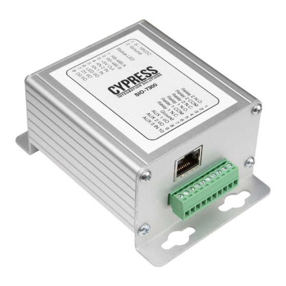
- Page 2 Cypress SIO-7300 - Specifications Overview The SIO-7300 is a TCP/IP device that supports Wiegand I/O, digital I/O, analog inputs and relay outputs, and is controlled by a network controller using the SIO protocol. The SIO-7300 allows the use of a single Wiegand reader without a traditional access control system.
- Page 3 Status LED Behavior RJ45 LED Behavior Input Mode Wiring Diagram Output Mode Wiring Diagram DIP Switches 11-12 Configuring Network Settings (Overview and Connecting to the SIO-7300) 13-15 Configuring Network Settings (Connecting via Telnet) 16-19 Configuring Network Settings (Connecting via web browser) 20-22 Configuring Network Settings (Default network settings)
- Page 4 Cypress SIO-7300 - Unit Dimensions SIO-7300 Enclosure Dimensions Dimensions in inches. 3.065" 2.770" ø 0.120 X 4 SIO-7300 Page 4 4.0625"...
- Page 5 Cypress SIO-7300 - Pin Designations 1 8 - 16VDC 2 Ground Relay 2 N.O. 1 Relay 2 COM 2 Status LED Relay 2 N.C. 3 Relay 1 N.O. 4 1 RS-485 A Relay 1 COM 5 2 RS-485 B Relay 1 N.C. 6...
- Page 6 Cypress SIO-7300 - Circuit Board Assembly Features RJ45 Port J2 Header J1 Header J3 Header DIP Switches Status LED Heat Sink Screw Page 6...
-
Page 7: Status Led
Off - SIO-7300 is not powered on. Configuration Mode Solid Green - SIO-7300 is powered on and configuration settings have been applied. Flashing Green - When the Network Settings are defaulted, the status LED will flash green for approximately 8 seconds until the network settings are applied. - Page 8 Cypress SIO-7300 - RJ45 LED Behavior RJ45 Port Activity LED (right) Link LED (left) Link LED (left) Activity LED (right) Color Meaning Color Meaning No Link No Activity Amber 10 Mbps Amber Half-Duplex Green 100 Mbps Green Full-Duplex Page 8...
-
Page 9: Host Device
Cypress SIO-7300 - Input Mode Wiring Diagram Host Device Network 1 8 - 16VDC 2 Ground Relay 2 N.O. 1 Relay 2 COM 2 Status LED Relay 2 N.C. 3 Relay 1 N.O. 4 1 RS-485 A Relay 1 COM 5 2 RS-485 B Relay 1 N.C. - Page 10 Cypress SIO-7300 - Output Mode Wiring Diagram Host Device Network 1 8 - 16VDC 2 Ground Relay 2 N.O. 1 Relay 2 COM 2 Status LED Relay 2 N.C. 3 Relay 1 N.O. 4 1 RS-485 A Relay 1 COM 5 2 RS-485 B Relay 1 N.C.
- Page 11 Overview The DIP Switches control the SIO-7300 data interface, I/O direction, and can be used to set the network parameters to their default state. The DIP Switches are located on the main board of the SIO-7300 circuit assembly. The circuit assembly needs to be removed from the enclosure in order to access the DIP Switches.
-
Page 12: Dip Switch Description
Default DIP Switch Settings The SIO-7300 is shipped in Run Mode. It is set to Data Input Mode, AUX 1 and AUX 2 are set as inputs, and the data interface is set to Wiegand. The Network Settings are set to their default parameters. - Page 13 Connecting to the SIO-7300 The SIO-7300 has a default IP address of 192.168.49.59. Telnet and the web browser need to be able to connect to this IP address, and the computer’s network settings need to be changed to be compatible with it. This is done through he Network and Sharing Center on Windows computers.
- Page 14 Cypress SIO-7300 - Configuring Network Settings (cont.) At the Network and Sharing Center, click on “Change adapter settings” on the left side of the screen. Disable any wireless network connections (if any are present) by right-clicking the wireless network, and select Disable from the drop-down menu.
- Page 15 Cypress SIO-7300 - Configuring Network Settings (cont.) Right-click on the Local Area Connection; the Local Area Connection Properties window will appear. Double-click on Internet Protocol Version 4; the IPv4 Properties window will appear. Select “Use the following IP address:” and enter the IP address 192.168.49.100 with a Subnet Mask of 255.255.255.0.
-
Page 16: Connecting Via Telnet
If/once Telnet is enabled, enter the Telnet command into Command Prompt. The Telnet command has two arguments, the IP address and the port number. The IP address is the IP address of the SIO-7300, by default it is 192.168.49.59. The SIO-7300 only accepts Telnet requests on port 9999. Enter the Telnet command and press enter. - Page 17 When the Telnet connection is successful, the screen will change to match the picture below. Press enter to proceed to the main menu. The main menu lists the sub menus. Most parameters concerning the SIO-7300 are in the Server, Channel 1, Expert, and Security menus. When finished changing the network settings, select option 9 to save and exit.
- Page 18 Cypress SIO-7300 - Configuring Network Settings (cont.) Below are the Server menu parameters. Notably, the Server menu is where the IP address is changed. Below are the the Channel 1 menu parameters. Page 18...
- Page 19 Cypress SIO-7300 - Configuring Network Settings (cont.) Below are the Expert menu parameters. Below are the Security menu parameters. Page 19...
-
Page 20: Connecting Via Web Browser
Connecting via Web Browser This example uses Google Chrome. Enter the IP address of the SIO-7300 into the address bar; the default IP address of the SIO-7300 is 192.168.49.59. The web browser will prompt the user login with a username and password. Since no username or password are necessary, simply click “Sign In”... - Page 21 Cypress SIO-7300 - Configuring Network Settings (cont.) The XPort main menu is pictured below. The sub menus are located on the left side of the screen. Click on Network, Server, and Connection to navigate to those menus. When finished changing network settings, click “Apply Settings”.
- Page 22 Cypress SIO-7300 - Configuring Network Settings (cont.) Below is the Server Settings menu. Below is the Connection Settings menu. Page 22...
-
Page 23: Default Network Settings
Cypress SIO-7300 - Configuring Network Settings (cont.) Default Network Settings Basic Parameters Hardware:……………………………Ethernet TPI IP Address:………………………192.168.49.59, no gateway set, netmask 255.255.255.0 DNS Server:………………………Not Set DHCP FQDN Option:………Disabled Security SNMP:………………………………………………Enabled SNMP Community Name:………Not Set Telnet Setup:…………………………Enabled TFTP Download:………………………Enabled Port 77FEh:………………………………Enabled 77FEh Access Mode:……………Read & Write Web Server:………………………………Enabled... - Page 24 Cypress SIO-7300 - Packet Structure The SIO-7300 accepts one TCP connection at a time on port 10001. The host software sends binary encoded data to the SIO-7300. If the data was formatted properly, the SIO-7300 will respond accordingly. If the SIO-7300 did not receive correctly formatted data, it will not respond.
- Page 25 Idle Status 0x15 (Poll) instead. After receiving reader data, the host must issue a Clear Reader Status 0x09 to the SIO-7300. If the SIO-7300 is in Wiegand Output Mode or has not received reader data, the SIO-7300 will reply with the Idle Status 0x15 (Response). 0x14...
- Page 26 Data Field Contents 0x16 Simulate 26 Bit 3 bytes This command is only valid when the SIO-7300 is configured for (Command) Wiegand Wiegand Output. The first byte controls the 8 bit facility code, and the next two bytes control the 15 bit badge number (big endian).
- Page 27 Despite references to “24-40 Bit” or “24-248”, the Data Formats can contain as little as 1 bit when sending Reader Data to the SIO-7300 in Data Output Mode. The SIO-7300 can receive as few as 4 bits when in Data Input Mode, this data will be in the 40 Bit Reader Data format.
- Page 28 16 (Status) 1 byte - The Status Field shows the command/response codes. 0x16 is the Simulate 26 Bit Wiegand command. This tells the SIO-7300 to output the 3 bytes of data in the Data Field as a 26 bit Wiegand read. The SIO-7300 will automatically generate the parity bits.
- Page 29 The values of the Analog 1 and 2 pins range from 0x00 to 0xFF (0 to 255). 0x00 represents 0V and 0xFF represents 5V. In this packet, the SIO-7300 is reporting that both the Analog 1 and 2 pins are at 5V.
- Page 30 Wiegand Output Below is the analysis of the Wiegand output from the SIO-7300. The analysis shows that the Wiegand output matches the data in the Simulate Wiegand 26 Bit command (Status 0x16). The Facility Code is 18 and the Card Number is 13398.
- Page 31 This example shows the polling sequences for the SIO-7300 in Data Input Mode. These polling sequences show the host device polling the SIO-7300 when it does and does not have reader data to report. The SIO-7300 is expecting and receives 26 bits of reader data.
- Page 32 The values of the Analog 1 and 2 pins range from 0x00 to 0xFF (0 to 255). 0x00 represents 0V and 0xFF represents 5V. In this packet, the SIO-7300 is reporting that both the Analog 1 and 2 pins are at 5V.
- Page 33 This polling sequence shows the proper sequence of commands and responses between the host device and the SIO-7300 when the SIO has reader data to report. The host device sends the Idle command (0x15) to the SIO, the SIO responds with the Reader Data Response (0x16), the host device then sends the Clear Read command (0x09) to reset the SIO so it is ready for the next set of reader data, finally the SIO responds with the Clear Read response (0x09)
- Page 34 1A 00 00 24 69 57 (Data) 6 bytes - The first byte is the length of the reader data the SIO-7300 received. The first byte is 0x1A, which is 26 bits. The next 5 bytes is the right justified reader data. In this example the SIO-7300 received 26 bits of reader data and responded to the host device with the data in the 26 bit format.
- Page 35 Sync Field). This packet is 10 bytes in length excluding the Sync Field, or 0x0A. F1 (Source) 1 byte - Address of the device the packet originated from. This packet is a command to the SIO-7300 from the host device (network controller). The host device has a static address of 0xF1.
- Page 36 F1 (Destination) 1 byte - Address of the device the packet is being sent to. The host device’s address is static, 0xF1. This packet is being sent from the SIO-7300 to the host device. 01 (Type) 1 byte - This field is set based on which device generated the message. The host device did not generate this message so the Type Field is set to 0x01.
- Page 37 Overview The SIO-7300 supports various I/O that are controlled by the first byte in the Data field. These I/O points are LED, AUX 1, AUX 2, AUX 3, Relay 1 and Relay 2. This section covers how to use these I/O points in Input and Output modes.
- Page 38 Input Data Bytes The state of the SIO-7300’s digital inputs are each represented by the state of a bit in the first byte of the Data Field in messages that contain an input payload, such as the Idle (0x15) response. If the associated bit is set to 1, then the output is activated (0V).
- Page 39 LED Output When the SIO-7300 is set to Data Input Mode the LED I/O pin is an output. The LED I/O pin is typically used to control a LED input on a credential reader or other similar device. The LED I/O pin is an active low digital output. The normal state is high (5V).
-
Page 40: Auxiliary Inputs
Cypress SIO-7300 - AUX I/O Auxiliary I/O Overview There are three Auxiliary I/O pins; AUX 1 I/O, AUX 2 I/O, and AUX 3 IN. The AUX 1 I/O and AUX 2 I/O pins can be configured as input or output pins with the DIP Switches during configuration. In configuration mode, DIP Switch 4 controls the I/O direction of the AUX 1 I/O pin, and DIP Switch 5 controls the I/O direction of the AUX 2 I/O pin. -
Page 41: Auxiliary Outputs
AUX 1 I/O and AUX 2 I/O pins can be configured as outputs. The diagram below shows the AUX 1 I/O and AUX 2 I/O pins connected to input pins on the access controller. When the SIO-7300 receives a command from the host device that contains the Output Control Byte the AUX 1 I/O and AUX 2 I/O pins will follow the state of the associated bit. - Page 42 Cypress SIO-7300 - Analog Inputs Analog Input Overview There are two Analog Input pins, AN 1 IN and AN 2 IN. The Analog Input pins are only inputs, they cannot be configured to be outputs. The values of the Analog Input pin are represented in the second and third bytes of the Data Field in the 0x15 Idle response.
-
Page 43: Analog Devices
Cypress SIO-7300 - Analog Inputs (cont.) Analog Devices Analog devices with a voltage output between 0-5V can be connected to the Analog Input pins, such as a thermometer or a pressure sensor. The diagram below shows an analog thermometer connected to the AN 2 IN pin. As the temperature changes the voltage output of the thermometer changes. - Page 44 Relay Outputs Overview The SIO-7300 has two dry contact relay outputs, Relay 1 and Relay 2. Each relay output is a Single Pole Double Throw (SPDT) relay and has three pins, Normally Open (N.O.), Common (COM), and Normally Closed (N.C.). Each relay output has a normal state and an active state.
- Page 45 Cypress SIO-7300 - Relay Outputs (cont.) Using a Relay Output as a Wet Contact The diagram below shows how to use the relay outputs as a wet contact. The power (red) line from the 24VDC is run through Relay 2. While Relay 2 is in the normal state Relay 2 COM and Relay 2 N.O. are not continuous and the power circuit is incomplete.
Need help?
Do you have a question about the SIO-7300 and is the answer not in the manual?
Questions and answers