Table of Contents
Advertisement
Quick Links
Advertisement
Table of Contents

Related Manuals for Kramer WP-210A


Summary of Contents for Kramer WP-210A
- Page 1 Kramer Electronics, Ltd. USER MANUAL Model: WP-210A XGA/Audio Line Driver...
-
Page 2: Table Of Contents
Figure 7: Connecting the Balanced Stereo Audio Output to an Unbalanced Acceptor Figure 8: Connecting the WP-210A Tables Table 1: WP-210A Front Panel Features Table 2: WP-210A Left Panel Table 3: WP-210A Right Panel Table 4: Technical Specifications of the WP-210A XGA/Audio Line Driver Contents... - Page 3 1 For example: model number AD2512C, part number 2535-000251 – No operator-serviceable parts inside unit. – Use only the Kramer Electronics input power – Disconnect power and unplug unit from wall 2900-9999992...
- Page 4 WP-220E, and WP-230. This addendum clarifies the correct color of the V sync and H sync coax cables. The color of the coax cables with all Kramer Wall Plates, including the WP-210, WP-210E, WP-210A, WP-210AE, WP-210AL, WP-220, WP-220E, WP-230 will be as follows: For V sync (vertical sync) –...
-
Page 5: Introduction
GROUP 6: Accessories and Rack Adapters; GROUP 7: Scan Converters and Scalers; and GROUP 8: Cables and Connectors 2 In addition to our active wall plate devices, Kramer’s WP series consists of passive wall plate and passive connection modules that work with the WP Frame and/or the VPM-2 XGA Line Driver wall plate 3 Download up-to-date Kramer user manuals from the Internet at this URL: http://www.kramerelectronics.com... -
Page 6: Your Wp-210A Xga/Audio Line Driver
(often associated with low quality cables) Avoiding interference from neighboring electrical appliances Positioning your WP-210A away from moisture, excessive sunlight and dust Your WP-210A XGA/Audio Line Driver This section defines the WP-210A XGA/Audio Line Driver: Front panel (see section 4.1) -
Page 7: Your Wp-210A Front Panel
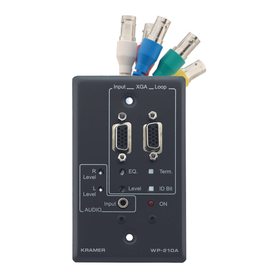
Your WP-210A XGA/Audio Line Driver 4.1 Your WP-210A Front Panel Figure 1 and Table 1 define the front panel of the WP-210A: Table 1: WP-210A Front Panel Features Feature Input HD15F Connector Potentiometer Level Potentiometer AUDIO R Level Trimmer AUDIO L Level Trimmer AUDIO Input 3.5mm Mini Jack Connects to the unbalanced stereo audio source... -
Page 8: Your Wp-210A Left Panel
Your WP-210A XGA/Audio Line Driver 4.2 Your WP-210A Left Panel Figure 2 and Table 2 define the left panel of the WP-210A: Figure 2: WP-210A Left Panel 4.3 Your WP-210A Right Panel Figure 3 and Table 3 define the right panel of the WP-210A:... -
Page 9: Using The Wp-210A Xga/Audio Line Driver
Using the WP-210A XGA/Audio Line Driver Using the WP-210A XGA/Audio Line Driver You can use your WP-210A XGA/Audio Line Driver, for example, in a conference room, as the example in Figure 4 illustrates: Figure 4: Example of Conference Room WP-210A Installation For details of how to: Install your WP-210A XGA/Audio Line Driver, see section 5.1... -
Page 10: Installing The Wp-210A Xga/Audio Line Driver
5. Insert the WP-210A directly into the wall box opening, and then mount the front panel securely using the screws. 1 The WP-210A could be used for component HDTV by connecting YPbPr in place of GBR, and not connecting H and V Figure 5: WP-210A RGBHV Outputs... -
Page 11: Operating The Wp-210A Xga/Audio Line Driver
1 Not supplied. The complete list of Kramer cables is on our Web site at http://www.kramerelectronics.com 2 Use a screwdriver to carefully rotate the Potentiometer, adjusting the appropriate level... -
Page 12: Figure 8: Connecting The Wp-210A
Using the WP-210A XGA/Audio Line Driver Figure 8: Connecting the WP-210A KRAMER: SIMPLE CREATIVE TECHNOLOGY... -
Page 13: Technical Specifications
WEIGHT: 0.3 kg (0.67 lbs.) approx ACCESSORIES: Power supply 1 Specifications are subject to change without notice Technical Specifications of the WP-210A XGA/Audio Line Driver AUDIO: Unbalanced stereo 3.5mm mini jack AUDIO: Balanced stereo terminal block connector AUDIO: 5.3Vpp AUDIO: AC... - Page 14 EXCLUSION OF DAMAGES The liability of Kramer for any effective products is limited to the repair or replacement of the product at our option. Kramer shall not be liable for: Damage to other property caused by defects in this product, damages based upon inconvenience, loss of use of the product, loss of time, commercial loss;...
- Page 15 For the latest information on our products and a list of Kramer distributors, visit our Web site: www.kramerelectronics.com, where updates to this user manual may be found. We welcome your questions, comments and feedback. Safety Warning: Disconnect the unit from the power supply before opening/servicing.
Need help?
Do you have a question about the WP-210A and is the answer not in the manual?
Questions and answers