Table of Contents
Advertisement
Quick Links
Advertisement
Table of Contents

Related Manuals for Kramer TBUS-1


Summary of Contents for Kramer TBUS-1
- Page 1 Kramer Electronics, Ltd. USER MANUAL Model: TBUS-1...
-
Page 2: Table Of Contents
Figure 3: TBUS-1 Connecting Surface Figure 4: Cutout Dimensions Figure 5: Inserting TBUS-1 into the Prepared Opening Figure 6: Securing the TBUS-1 into the Prepared Opening Tables Table 1: TBUS-1 Table Connection Bus Features Table 2: TBUS-1 Connecting Surface Features... -
Page 3: Introduction
GROUP 6: Accessories and Rack Adapters; GROUP 7: Scan Converters and Scalers; and GROUP 8: Cables and Connectors 2 Download up-to-date Kramer user manuals from our Web site: http://www.kramerelectronics.com 3 The complete list of Kramer cables is on our Web site at http://www.kramerelectronics.com Introduction... - Page 4 Getting Started KRAMER: SIMPLE CREATIVE TECHNOLOGY...
-
Page 5: Overview
Kramer TBUS-1 away from moisture, excessive sunlight and dust 1 The complete list of Kramer wall plate devices, for designing the Connecting Surface, can be found on our Web site at http://www.kramerelectronics.com Overview... -
Page 6: Your Tbus-1 Connection Bus
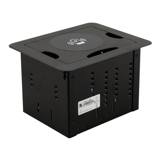
Your TBUS-1 Connection Bus Figure 2 and Table 1 define the TBUS-1 unit: Figure 2: TBUS-1 Table Connection Bus Table 1: TBUS-1 Table Connection Bus Features Feature Connecting Surface Black Textured Lid Outer Rim Enclosure Height Adjustment Screws Rubber Protectors... -
Page 7: Connecting The Tbus-1
Mount the required wall plate items (see section 5.2) Set the height of the Connecting Surface (see section 5.3) Insert the TBUS-1 through the hole (see section 5.4) Connect the cables (see section 5.5) Secure the unit to the table (see section 5.6) -
Page 8: Cutting An Opening
Any of the plates mounted to the Connecting Surface can be rearranged or removed and replaced with Kramer passive wall plates for interfacing A/V type signals. 1 The complete list of Kramer wall plates and module connectors is on our Web site at http://www.kramerelectronics.com Connecting the TBUS-1 130+2mm (5.12+0.08") -
Page 9: Adjusting The Height Of The Connecting Surface
1 Bring the Connecting Surface closer to the table top or lower it, giving space for bulky devices or cables Connecting the TBUS-1 to fit your needs, do the following:... -
Page 10: Inserting The Tbus-1 Through The Cut Out Opening
5.4 Inserting the TBUS-1 Through the Cut Out Opening After installing the required devices and adjusting the Connecting Surface height, carefully insert the unit into the prepared opening, as illustrated in Figure 5. Figure 5: Inserting TBUS-1 into the Prepared Opening 5.5 Installing the Cables... -
Page 11: Securing The Tbus-1 Enclosure To The Table
Power cord, six self-locking ties OPTIONS: Passive wall plates and interfaces 1 Specifications are subject to change without notice 2 The complete list of Kramer wall plates and module connectors is on our Web site at http://www.kramerelectronics.com Technical Specifications of the TBUS-1... - Page 12 EXCLUSION OF DAMAGES The liability of Kramer for any effective products is limited to the repair or replacement of the product at our option. Kramer shall not be liable for: Damage to other property caused by defects in this product, damages based upon inconvenience, loss of use of the product, loss of time, commercial loss;...
- Page 13 For the latest information on our products and a list of Kramer distributors, visit our Web site: www.kramerelectronics.com, where updates to this user manual may be found. We welcome your questions, comments and feedback. Safety Warning: Disconnect the unit from the power supply before opening/servicing.
Need help?
Do you have a question about the TBUS-1 and is the answer not in the manual?
Questions and answers