
Related Manuals for Kramer FC-5


Summary of Contents for Kramer FC-5
-
Page 1: User Manual
KR AMER ELECTRON ICS LT D. USER MANUAL MODEL: FC-5 Protocol Translator P/N: 2900-000148 Rev 3... -
Page 3: Table Of Contents
Your FC-5 Protocol Translator Configuring the Kramer FC-5 Manager Software Installing and Running the Kramer FC-5 Manager Software Using the Translation List Window Connecting a PC (CONFIG Port) ... -
Page 4: Introduction
GROUP 7: Scan Converters and Scalers; GROUP 8: Cables and Connectors; GROUP 9: Room Connectivity; GROUP 10: Accessories and Rack Adapters and GROUP 11: Sierra Products. Congratulations on purchasing your Kramer FC-5 Protocol Translator, which is ideal for the following typical applications: •... -
Page 5: Getting Started
(often associated with low quality cables) • Avoid interference from neighboring electrical appliances that may adversely influence signal quality • Position your Kramer FC-5 away from moisture, excessive sunlight and dust FC-5 - Getting Started... -
Page 6: Overview
Overview The FC-5 is a protocol translator designed to make an RS-232 controlled machine (Kramer and non-Kramer products) compatible with other RS-232 based protocols. By default the unit comes configured with two translation drivers, includes a PC based software program for user configuration, and has two relays and eleven contact closure control connections. -
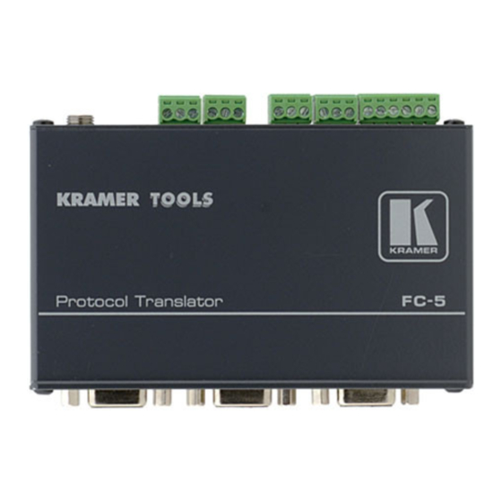
Page 7: Your Fc-5 Protocol Translator
5.2) +12V DC connector for powering the unit 12V DC COM1 9-pin D-type RS-232 port Connects to the Kramer or other device COM2 9-pin D-type RS-232 port Connects to the Kramer or other device CONFIG 9-pin D-type port Connects to the RS-232 port on a PC... -
Page 8: Figure 2: Fc-5 Underside
Figure 2: FC-5 Underside Feature Function Switch Slide all 3 switches down to set to OFF (Normal mode, default). Slide all 3 switches Switch up to set to ON (Program mode) Switch FC-5 - Your FC-5 Protocol Translator... -
Page 9: Configuring The Kramer Fc-5 Manager Software
Installing and Running the Kramer FC-5 Manager Software To install the FC-5 Manager software: 1. Insert the CD-ROM in the CD-ROM drive; double click the FC-5 Manager icon. The Port selection window appears: Figure 3: Port Selection Window 2. Choose the appropriate COM port for configuration via the serial cable and click OK. -
Page 10: Using The Translation List Window
Closes the Command Translation List window Assign Button Transmits the complete set to the COM ports of the FC-5 unit The data is assigned to the “translation set” according to the DIP-switch setting at the time that the Assign button is pressed... -
Page 11: Figure 5: New/Open File Menu Command Dialog Box
Figure 5: New/Open File Menu Command Dialog Box 5.2.1 Entering Data in the New Command Window Figure 6 defines the New Command window: Figure 6: New Command Window FC-5 - Configuring the Kramer FC-5 Manager Software... -
Page 12: Figure 7: Edit Command Window
Note: To enter invisible characters in ASCII mode (such as "ENTER") place the cursor in that square and press the appropriate key on the keyboard. 5.2.2 Editing Data in the Command Window Figure 7 defines the Edit Command window: Figure 7: Edit Command Window FC-5 - Configuring the Kramer FC-5 Manager Software... -
Page 13: Figure 8: Remove Command Prompt
To erase a command from the Command Translation List window, select the relevant command and then click Remove. Click Yes to the Remove prompt message (see Figure Figure 8: Remove Command Prompt FC-5 - Configuring the Kramer FC-5 Manager Software... -
Page 14: Connecting A Pc (Config Port)
2, and pin to pin need be connected) to the RS-232 9-pin D-sub port on the PC. Note: There is no need to connect any other pins. Figure 10: Crossed Cable RS-232 Connection FC-5 - Configuring the Kramer FC-5 Manager Software... -
Page 15: Setting The Dip-Switches
Determines the settings of the translation set 3, 4 Reserved Figure 12: Translation Set DIP-Switches Translation Translation Translation Translation Set 1 Set 2 Set 3 Set 4 Generic to Sierra Video Systems Kramer 2000 to Kramer 2000 (default) FC-5 - Configuring the Kramer FC-5 Manager Software... -
Page 16: Assigning The Translation List Driver Commands
This process can take several minutes. During the process the “Assign” button of the Kramer FC-5 Manager software application flashes, and the STATUS LED of the FC-5 unit also flashes. At the end of this process the following message appears: “Assigned Successfully!”... -
Page 17: Using The
Section 6.4 Transmitting Commands via a PC or Remote Controller You can use your FC-5 to transmit commands via a PC or remote controller: Figure 13: Transmitting Commands via a PC or Remote Controller Connect a PC or Remote Controller to the COM1 port and a controlled unit is connected to the COM2 port. -
Page 18: Transmitting Commands Via The Contact Closure
Transmitting Commands via the Contact Closure You can use the FC-5 to transmit commands via the contact closure (see also Section 6.4): Figure 14: Transmitting Commands via the Contact closure The INPUTS contact closure remote control pins let you temporarily route an input to the output by momentarily attaching an input to the GND (Ground) pin (do not connect more than one PIN to the Ground PIN at the same time). -
Page 19: Transmitting Commands Via The Relays
Transmitting Commands via the Relays You can use your FC-5 to transmit commands via the relays: Figure 15: Transmitting Commands via the Relays A PC or Remote Controller is connected to the COM1 port. Relay 1 is connected to the blinds, and relay 2 is connected to the lighting system. On each 3-pole... -
Page 20: Transmitting Commands Via The Contact Closure And Relays
Transmitting Commands via the Contact Closure and Relays You can use your FC-5 to transmit commands via the contact closure to the relays, and to a projector via RS-232: Figure 17: Transmitting Commands via the Contact closure and Relays The INPUTS contact closure remote control pins let you switch commands to the relays, and via RS-232. -
Page 21: Upgrading The Fc-5 Firmware
Upgrading the FC-5 Firmware The FC-5 firmware is located in FLASH memory, which lets you upgrade to the latest Kramer firmware version in minutes! The process involves: • Downloading from the Internet (see Section 7.1) • Connecting the PC to the RS-232 CONFIG port (see Section 7.2) -
Page 22: Upgrading Firmware
12), slide all three switches to OFF (Normal Mode), using a screwdriver. 8. Connect the 12V DC power adapter to the power socket and connect the adapter to the mains electricity. The FC-5 now functions with the upgraded firmware. FC-5 - Upgrading the FC-5 Firmware... -
Page 23: Technical Specifications
12cm x 7.15cm x 2.76cm (4.7” x 2.8” x 1.08”) W, D, H WEIGHT: 0.3kg (0.67lbs) approx ACCESSORIES: Power supply, mounting bracket, Kramer's Windows®-based configuration software, null modem connector OPTIONS: RK-3T 19" rack adapter Specifications are subject to change without notice at http://www.kramerelectronics.com... - Page 24 1. Any product which is not distributed by us or which is not purchased from an authorized Kramer dealer. If you are uncertain as to whether a dealer is authorized, please contact Kramer at one of the agents listed in the Web site www.kramerelectronics.com.
- Page 25 For the latest information on our products and a list of Kramer distributors, visit our Web site where updates to this user manual may be found. We welcome your questions, comments, and feedback. Web site: www.kramerelectronics.com E-mail: info@kramerel.com SAFETY WARNING...
Need help?
Do you have a question about the FC-5 and is the answer not in the manual?
Questions and answers