
Related Manuals for Kramer WP-500


Summary of Contents for Kramer WP-500
-
Page 1: User Manual
Kramer Electronics, Ltd. USER MANUAL Model: WP-500 Wall Plate Solution for Simple Room Control and Signal Switching... -
Page 2: Table Of Contents
Technical Specifications Figures Figure 1: WP-500 Front Panel Figure 2: WP-500 Rear Panel Figure 3: Connecting the WP-500 Front Panel Figure 4: Connecting the WP-500 Rear Panel Figure 5: Setting the Microphone Mode Switch Tables Table 1: WP-500 Front Panel Features... -
Page 3: Introduction
We recommend that you review the contents of this user manual. Overview The WP-500 is an all-in-one AV solution for classrooms, training rooms and similar simple AV installations. It enables remote projector or flat panel control and the routing of one of three A/V sources to the inputs of a display device via the front panel buttons. - Page 4 Kramer WP-500 away from moisture, excessive sunlight and dust 1 Kramer Site-CTRL is a powerful A/V asset management tool. It offers real-time network monitoring and control of Kramer Master controllers installed at an A/V site and all the connected A/V equipment. The Kramer Site-CTRL downloadable version can monitor and control up to 100 Kramer Master controllers.
-
Page 5: Defining The Wp-500
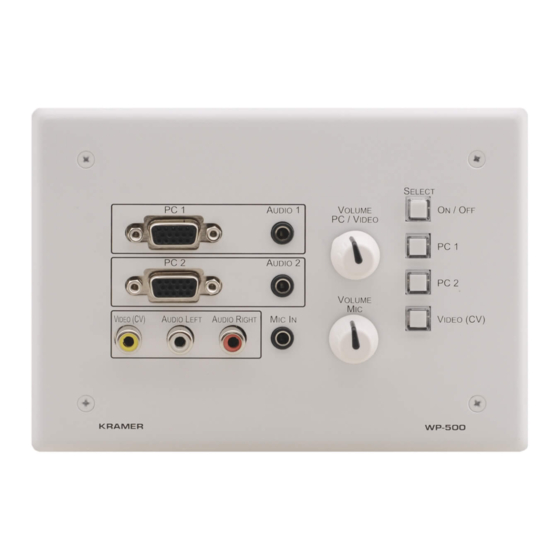
Defining the WP-500 Defining the WP-500 Figure 1 Table 1 define the WP-500 front panel: Figure 1: WP-500 Front Panel Table 1: WP-500 Front Panel Features Feature Function MIC IN 3.5mm mini jack Connect to microphone Video and Audio AUDIO RIGHT... -
Page 6: Figure 2: Wp-500 Rear Panel
1 Both output ports are identical 2 This operation should be carried out by authorized Kramer technical personnel or by an external system integrator, and requires removal of the device from the wall by unscrewing the four wall mount screws 3 Using a small screwdriver 4 Disconnect the power and then connect it while pressing the Factory Reset button. -
Page 7: 4.1 The Usb Port
VIDEO (PC) RCA and AUDIO LEFT and RIGHT RCA connectors, respectively A microphone to the MIC IN 3.5mm mini jack (see section 5.1.1) 1 By the system integrator only 2 By authorized Kramer technical personnel or by an external system integrator... -
Page 8: Figure 3: Connecting The Wp-500 Front Panel
Using Your WP-500 Figure 3: Connecting the WP-500 Front Panel 2. On the rear panel, connect the display device (for example, a projector) as follows. Connect the: VGA (PC) OUTPUT to the PC Graphics (15-pin HD connector or RGBHV connector) input on the projector ... -
Page 9: Figure 4: Connecting The Wp-500 Rear Panel
Using Your WP-500 Figure 4: Connecting the WP-500 Rear Panel... -
Page 10: Connecting The Microphone
The Dyn/Cond mode switch is located behind the front panel on the lower left side of the MIC IN 3.5mm jack, as illustrated in Figure It is recommended to set the mic mode switch before mounting the WP-500 front panel. Cond... -
Page 11: Operating The Wp-500
3 The macro sequence can be carried out instantly or can take a while, depending on the delay times included in the sequence 4 This is a two toggle button. a macro can be assigned for each toggle of the button via the Kramer K-Config software... -
Page 12: Technical Specifications
DIMENSIONS: 16.2cm x 3.4cm x 11.4cm (6.37" x 1.34" x 4.49", W, D, H) WEIGHT: 0.14kg (0.31lbs) approx. ACCESSORIES: Power supply, screwdriver, Kramer K-Config Windows®-based configuration software OPTIONS: 12V DC, 0.5A Power supply , USB cable 3' (0.91m) , WP-500 Installation cable, FC-200 XGA EDID Copier, Site-CTRL™... - Page 13 EXCLUSION OF DAMAGES The liability of Kramer for any effective products is limited to the repair or replacement of the product at our option. Kramer shall not be liable for: 1. Damage to other property caused by defects in this product, damages based upon inconvenience, loss of use of the product, loss of time, commercial loss;...
- Page 14 For the latest information on our products and a list of Kramer distributors, visit our Web site: www.kramerelectronics.com, where updates to this user manual may be found. We welcome your questions, comments and feedback. Safety Warning: Disconnect the unit from the power supply before opening/servicing.
Need help?
Do you have a question about the WP-500 and is the answer not in the manual?
Questions and answers