Advertisement
Quick Links
EN
Instructions
Rexroth NYS04.1-ST-01-LMS-SERCOS-NY4078
1
About this Documentation
1.1 Overview – target groups & product phases
The target groups, product phases and activi-
ties that can refer to this document are marked
in rounded boxes in the following figure.
Mounting
Product phases
Selection
(assembly/installation)
Presales Aftersales
Design engineer
Mechanic/
electrician
Programmer
Technologist
Process
specialist
Target groups
To select
To unpack
To prepare
To mount
Activities
To design
To install
To construct
1.2 Intended audience
This document explains technical and service
personnel of the machine builder how to safely
install the system housing mechanically and
electrically. This document is not the usage
manual.
1.3 Availability
These Instructions are part of the NYS04.1-ST-
01-LMS-SERCOS-NY4078 system housing
product delivery and must always be available
for the user.
If the system housing is handed over to another
person, these Instructions must be handed over
as well.
October 21, 2016
Bosch Rexroth AG
Electric Drives and Controls
Bgm.-Dr.-Nebel-Str. 2
D-97816 Lohr am Main
Telefon +49 (0)9352-18-0
Telefax +49 (0)9352-18-8400
www.boschrexroth.com
Engineering
Operation
Commissioning
De-commissioning
Programmer
Commissioning engineer
Technologist
Process specialist
Machine
operator
Maintenance
technician
Mechanic/
electrician
Service
Disposal company
To parameterize
To optimize
To operate
To dismount
To program
To test
To maintain
To dispose
To remove
To configure
faults
To create
To simulate
the program
1.4 Included parts
Type code
NYS04.1-ST-01-LMS-SERCOS-
NY4078
DOK-NY4000-LMS*SERCOS*-IT07-
EN-P
Headers for the 24V System and SE connectors
are also included.
1.5 Variations
These Instructions apply to the NYCe 4000
system housings with the following type code:
• NYS04.1-ST-01-LMS-SERCOS-NY4078
1.6 Further available documentation
Title and type code
Rexroth NYCe 4000
Hardware System Manual
DOK-NY4000-HW***SYSTEM-PRRS-EN-E
Rexroth NYCe 4000
Standard Housings & Accessories Manual
DOK-NY4000-HOUSING*ACC-PRRS-EN-E
1.7 Additional parts
Motion Control Units, host adapter, SERCOS
III Master module, fan unit, connection cables,
and more are listed in the project planning
manuals or on
2
Product Identification and Scope of
Delivery
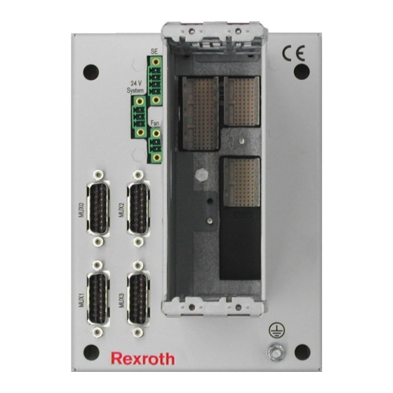
2.1 Product identification
The NYS04.1-ST-01-LMS-SERCOS-NY4078
has two slots, one for the Motion Control Unit
(MCU) and one for the SERCOS III Master
module.
Page 1 of 10
Material
number
R911172617
R911336853
Material number
R911337671
R911337672
www.boschrexroth.com
R911336853-07_BAL_DOC
Description
System housing
Instructions
Advertisement

Related Manuals for Bosch Rexroth NYS04.1-ST-01-LMS-SERCOS-NY4078


Summary of Contents for Bosch Rexroth NYS04.1-ST-01-LMS-SERCOS-NY4078
- Page 1 1.4 Included parts Bosch Rexroth AG Electric Drives and Controls Type code Material Description Bgm.-Dr.-Nebel-Str. 2 number D-97816 Lohr am Main NYS04.1-ST-01-LMS-SERCOS- R911172617 System housing Telefon +49 (0)9352-18-0 NY4078 Telefax +49 (0)9352-18-8400 DOK-NY4000-LMS*SERCOS*-IT07- R911336853 Instructions EN-P www.boschrexroth.com Headers for the 24V System and SE connectors are also included.
- Page 2 Logotype Type code Division number / plant number Change index Rated voltage and current UL marking Consult documentation marking Degrees of protection provided by enclosure (IP code) Designation of origin Date of manufacture (yyWww) Rexroth bar code Serial number Company address Test marking CE marking Material number...
-
Page 3: Intended Use
The safety alert symbol (a triangle with an ex- Typecode Material Description number clamation point), which precedes the signal NYA04.1-FAN-1DRV- R911328062 Fan unit - 1 drive slot NY4922/00 words danger, warning and caution is used to NYA04.1-STRAIN-RELIEF- R911322873 Strain relief for alert the reader to personal injury hazards. - Page 4 Standards in a test assembly that conforms with the standards. These Rexroth products are built-in 8.1 Used standards devices for a product for the final user. The test The components of the system housing corre- results cannot be transferred to every state as spond to the following standard.
- Page 5 Interfaces 9.5 MUX – LMS MUX Control connection These connectors connect the analog output 9.1 Overview signals and digital input selection lines to con- Designation Connection type Connection Connection trol the LMS MUX. on base plate (base plate) (cable) • MUX0 connects analog input 0 and 1. 24V System 24V DC system 3-pin male...
- Page 6 Power supplies must be switched on/off with the disconnecting device installed in the cabinet. The system housing may only be used as build-in equipment in a cabinet, which means that the end-user must provide a suitable fire and electrical safe enclosure. The safety of any system incorporating the system housing is the responsibility of the assembler of the system.
- Page 7 ≥ 100 mm 10.3 Mechanical removal of the system housing Make sure that all power supplies are switched off before you remove the system housing. Then disconnect the 24V System power supply connector. Finally, disconnect all re- maining connectors and protective earth con- nections.
- Page 8 • The switch or circuit breaker must be marked as the disconnecting device for the system housing power supply. 11 Commissioning - Check that the system housing is mechani- cally solid mounted in the machine. - Verify that the protective earth connection is correctly connected.
- Page 9 15.1 Products Our service department at our main facility Our products can be returned to us free of Bosch Rexroth AG charge for disposal. It is a precondition, how- Bgm.-Dr.-Nebel-Str.2 ever, that the products are free of oil, grease or D-97816 Lohr am Main other dirt.
- Page 10 Notes R911336853-07_BAL_DOC October 21, 2016 Page 10 of 10...
Need help?
Do you have a question about the Rexroth NYS04.1-ST-01-LMS-SERCOS-NY4078 and is the answer not in the manual?
Questions and answers