Advertisement
Quick Links
1 | Overview
The B901 Access Control module is a fully supervised SDI2/SDI
device that allows access control integration for compatible control
panels. Each module can store up to 2000 user tokens (on SDI2),
each with a different access level for each door. Authority for access
is controlled by the user's authority level, the time of day, the state
of the door, and the armed state to the module.
Compatible Credential Formats
37 bit
HID H10304 (With Site Code)
37 bit
HID H10302 (No Site Code)
26 bit
HID H10301 EM-EM4200 (3-byte or 5-byte)
1
2
3
8
RELAY
READER
NC
C
N0
T+
COM
ZN+
RTE
COM
REX
12V
5.2V
DATA0 DATA1 BUZZER LED
6
7
5
4
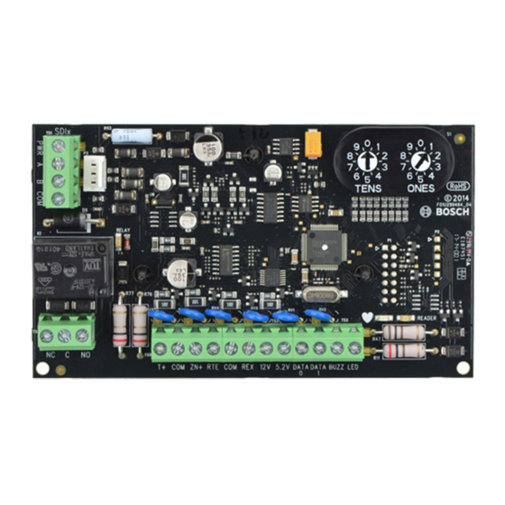
Figure 1.1: Access control module
Callout ― Description
1 ― Terminal connector
2 ― Interconnect wiring connectors
3 ― Address switch
4 ― Reader LED
5 ― Heartbeat LED (blue)
6 ― Reader and door terminals
7 ― Relay terminals
8 ― Relay LED
2 | Address settings
Two address switches determine the address for the B901
Access Control Module. The control panel uses the address for
communications. The address also determines the output numbers. Use
a slotted screwdriver to set the two address switches.
NOTICE!
The module reads the address switch setting only during
power up. If you change the switches after you apply power to
the module, you must cycle the power to the module in order
for the new setting to be enabled.
Set the address switches per the control panel configuration. If
multiple B901 modules reside on the same system, each B901 module
must have a unique address. Figure 2.1 shows the address switch
settings for address 01.
Figure 2.1: Address switches
2.1 | Valid addresses for SDI2
Valid B901 addresses are dependant on the number of modules allowed
by a particular control panel.
Control panel
Valid B901
Designation
addresses
B9512G/B9512G-E
01 - 32
Devices 1 - 32
B8512G/B8512G-E
01 - 08
Devices 1 - 8
Control panel
Valid B901
Designation
addresses
B6512
01 - 04
Devices 1 - 4
2.2 | Valid addresses for SDI
Valid B901 addresses are dependant on the number of modules allowed
and the desired failure mode (Fail Safe, Fail Secure) by a particular
control panel.
Control panel
Valid B901
Designation
addresses
B9512G/B9512G-E/
81 - 88
Devices 1 - 8
B8512G/B8512G-E
Fail Safe mode =
D9412GV4/D7412GV4
door unlocked
D9412GV3/D7412GV3
91-98
Devices 1 - 8 Fail Se-
D9412GV2/D7412GV2,
cure = door locked
D9000
3 | Installation
After you set the address switch for the proper address, install the
module in the enclosure, and then wire it to the control panel.
CAUTION!
Remove all power (AC and battery) before making any
connections. Failure to do so might result in personal
injury and/or equipment damage.
NOTICE!
B901 tamper generates an SDI - "Missing Door" or an
SDI2 - "Module Tamper" message (if Enclosure Tamper
parameter is set to Yes).
3.1 | Mount the module in the enclosure
Mount the module into the enclosure's 3-hole mounting pattern using
the supplied mounting screws and mounting bracket.
Refer to Figure 3.1.
Figure 3.1: Mounting the module in the enclosure
Callout ― Description
1 ― Module with mounting bracket installed
2 ― Enclosure
3 ― Mounting screws (3)
3.2 | Mount the access card reader
Refer to your access card reader installation instructions for proper
installation and maintenance procedures related to your supported
card reader.
3.3 | Wire to the SDI2 control panel
When you wire the module to a control panel, use the control panel
terminals labeled R, Y, G, B (PWR, A, B, COM). Connect them to the
module terminals labeled R, Y, G, B (PWR, A, B, COM). Use either
terminal strip wiring or interconnect wiring connector to the control
panel. Do not use both. Refer to Figures 3.2 - 3.3.
1
1
3
3
2
R
PWR+/R
29
PWR+/R
29
Y
A/Y
28
A/Y
28
G
4
B/G
27
B/G
27
B
COM/B
26
COM/B
26
Battery R
Battery R
er
t
year
t
er
t
year
t
one or t
one or t
SDI2
SDI2
tterie
tterie
Battery R
Battery R
er
t
year
t
er
t
year
t
one or t
one or t
PWR+/R
26
PWR+/R
26
tterie
tterie
WARNING!
WARNING!
A/Y
25
A/Y
25
Multi-Battery
Multi-Battery
installation requires
installation requires
Dual Battery
rnes
Dual Battery
rnes
I
r
B/G
24
I
r
B/G
24
ir
r
ir
r
Battery R
Battery R
er
t
year
t
COM/B
23
er
t
year
t
COM/B
23
one or t
one or t
tterie
tterie
ZONEX
TAMPER
RESET
ZONEX
TAMPER
RESET
Figure 3.2: SDI2 wiring from control panel to B901
Callout ― Description
1 ― Bosch control panel (B9512G shown)
2 ― Terminal wiring
3 ― B901 Access Control Module
4 ― Interconnect cable (P/N: F01U79745) (included)
3.4 | Wire to the SDI control panel
1
1
4
3
WARNING
WARNING
To prevent risk o
To prevent risk o
D9412GV3
electric shock,
electric shock,
disconnect AC
2
D9412GV3
disconnect AC
power and
power and
telephone lines
telephone lines
be ore servicing.
be ore servicing.
Commercial Protected-Premises Control Panel
SDI Connector
Commercial Protected-Premises Control Panel
SDI Connector
Reset Pin
Reset Pin
Minimum system re uirements or Classi ication in accordance with
ANSI SIA CP-01-2007:
Disable all except Battery
Minimum system re uirements or Classi ication in accordance with
Disable all except Battery
UL Listed and Classi ied control unit Model D9412GV3, D7412GV3, or
Charging and Programming
ANSI SIA CP-01-2007:
Charging and Programming
D7212GV3
D7212GV3
UL Listed and Classi ied control unit Model D9412GV3, D7412GV3, or
UL Listed and Classi ied keyp ad Model D1256, D1257, D1260, D1255,
UL Listed and Classi ied keyp ad Model D1256, D1257, D1260, D1255,
D1255R, or D1255RW
PERIPHERAL DEVICE CONNECTIONS
D1255R, or D1255RW
PERIPHERAL DEVICE CONNECTIONS
RED
POWER +
R
R
RED
POWER +
Y
YELLOW
DATA BUS A
Y
YELLOW
DATA BUS A
G
GREEN
DATA BUS B
G
DATA BUS B
GREEN
B
Battery: Replace every 3 to
BLACK
COMMON
B
Battery: Replace every 3 to
BLACK
COMMON
5 years with one or two Model
5 years with one or two Model
D126 or D1218 12 V Lead Acid
D126 or D1218 12 V Lead Acid
Batteries.
NFPA
ZONEX OUT 1
Batteries.
NFPA
ZONEX OUT 1
Style 4.0
Style 4.0
Signaling
Signaling
Line
ZONEX IN 1
Line
Circuits
Circuits
ZONEX IN 1
Not suitable or remote st ation protected premises
Not suitable or remote st ation protected premises
services where separate transmission circuits
26
services where separate transmission circuits
ZONEX OUT 2
ZONEX OUT 2
26
D9412GV3 Control Panel is UL Listed For
D9412GV3 Control Panel is UL Listed For
Central Station, Remote Station, Local,
25
Central Station, Remote Station, Local,
Auxiliary,
ZONEX IN 2
25
Auxiliary,
ZONEX IN 2
25
25
Proprietary, and Household Fire Alarm, and
Proprietary, and Household Fire Alarm, and
ZONEX POWER +
24
24
ZONEX POWER +
VOLTAGE RANGES
ZONEX COMMON
23
VOLTAGE RANGES
Open
3.7 - 5.0 VDC
Short
0.0 - 1.3 VDC
Open
3.7 - 5.0 VDC
Short
0.0 - 1.3 VDC
ZONEX COMMON
23
Normal
2.0 - 3.0 VDC
Normal
2.0 - 3.0 VDC
Point 4
Point 5 Point 6
Point 7 Point 8
Point 8, S3 Option
Point 4
Point 5 Point 6
Point 7 Point 8
Point 8, S3 Option
Operation Monitor LED
Operation Monitor LED
Pulses when Normal
Pulses when Normal
15
16
17
18
19
20
21
22
Flickers when Ringing
15
16
17
18
19
20
21
22
Flickers when Ringing
GREEN
GREEN
Figure 3.3: SDI wiring from control panel to B901
Callout ― Description
1 ― Bosch control panel (GV3 shown)
2 ― Terminal wiring
3 ― B901 Access Control Module
4 ― Interconnect cable (P/N: F01U79745) (included)
3.5 | Wire to the card reader
Use the terminals labeled LED, DATA1, DATA0, 5.2V or 12V, COM, and T+
when wiring the module to a card reader. Refer to Figure 3.4.
2
3
1
P
B
R
G
W
Br
Figure 3.4: Wiring the card reader to the B901
Callout ― Description
1 ― Card reader (ARD-AYK12 shown)
2 ― Terminal wiring
3 ― B901 Access Control Module
3.6 | Wire to 12VDC power supply (optional)
Refer to Figure 3.5 to wire additional power to a regulated power-
limited power supply for fire protective signaling units and commercial/
residential burglar units.
2
1
The syst
contr
DAC, OT, N
This eq
OUTPUT
7
Alar
B (2)
W
OUTPUT
8
RELAY C
C (3)
B
servicing.
9
COMMON
10
EARTH GROUND
WARNING!
W
Multi-Battery
installation requires
Model D122 or D122L
equipment.
B
Dual Battery Harness.
Improper installation
any output must be
can be a fire hazard .
supervised.
Figure 3.5: Wiring the card reader to the B901
Callout ― Description
1 ― Control panel COM terminal (B9512G shown)
2 ― 12 VDC regulated power-limited power supply (B520 shown)
3 ― Terminal wiring (PWR and COM terminal wiring)
4 ― B901 Access Control Module
3
NOTICE!
R
Use only Access Control listed power supplies for powering
Y
G
B
door strikes.
3.7 | Wire to the door strike
A relay provides a dry contact single pull double throw output. Some
strikes require a closed circuit to unlock the door, while others require
an open circuit to unlock the door.
•
Common (C). For 12/24 VDC strikes, provide input power here
from the power supply. Refer to Figure 3.6.
•
Normally closed (NC). For door strikes that require an interruption
of power to open. Connect the positive side of the door strike to
the NC terminal. Refer to Figure 3.6.
•
Normally open (NO). For door strikes that require power to open.
Connect the positive side of the door strike to the NO terminal.
Refer to Figure 3.6.
1
1
2
DOOR
DOOR
3
5
Figure 3.6: Wiring the door strike to the B901
Callout ― Description
1 ― Door
2 ― B901 door lock relay terminal
3 ― B901 terminal
4 ― AUX PWR terminal (12 VDC) (B520 shown)
5 ― Door strike (12 VDC)
3
4
R
4
2
3
5
Advertisement

Related Manuals for Bosch B901


Summary of Contents for Bosch B901
- Page 1 Authority for access is controlled by the user’s authority level, the time of day, the state of the door, and the armed state to the module. Valid B901 addresses are dependant on the number of modules allowed PWR+/R PWR+/R...
- Page 2 Canada CAN/ULC S303 - Local Burglar Alarm Units and Systems CAN/ULC S304 - Signal Receiving Centre and Premise Alarm After you wire the module, power up the system and configure the B901 Control Units using Remote Programming Software (RPS) to assign the module to an assigned area.
Need help?
Do you have a question about the B901 and is the answer not in the manual?
Questions and answers